
This “Quick Start” article will not be so short, but it will contain a lot of practical and useful knowledge: 3D model from photos. We will take a look at how a photogrammetry software creates a 3D reconstruction from digital photos; what free software is available and what you need to know about them. We will talk about the steps to generate 3D model from photos, as well as the post-processing of the 3D model. Remember that the modeling will only be as good as the data collection, i.e. taking the photos. If you have missed, make sure to read our previous articles in the photogrammetry topic: Photogrammetry in general and taking photos for photogrammetry use.
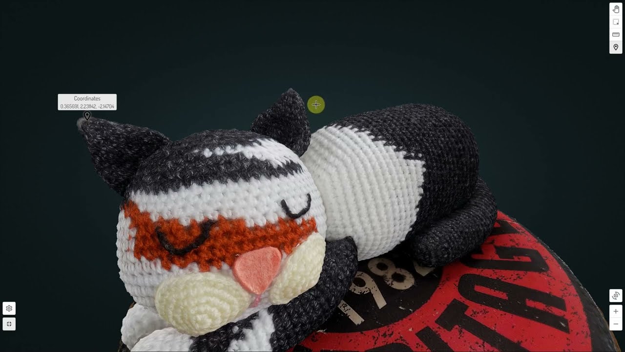
Do you want to know how the below model of Pete the cat was made? If your answer is yes, then – after walking around Pete virtually – be sure to continue reading the article to learn about the magic of creating a 3D model from photos. You can also view Pete’s model interactively and download it for free from SurveyTransfer by clicking HERE.
Sidenote: In the case of a 3D model from photos, you can get the raw images on our own developed SurveyTransfer data sharing! 🙂
PHOTOGRAMMETRY SOFTWARE that can be used to create 3D model from photos
Without claiming to be complete, I have collected free software that you can use to create 3D model from photos, point clouds, and with some of them, orthophotos, DEMs.
| Name | Type | OS |
| COLMAP | Aerial and ground | Windows, macOS, Linux |
| Meshroom | Aerial and ground | Windows, Linux |
| MicMac | Aerial and ground | Windows, macOS, Linux |
| Multi-View Environment | Aerial and ground | Windows, macOS |
| OpenMVG | Aerial and ground | Windows, macOS, Linux |
| Regard3D | Aerial and ground | Windows, macOS, Linux |
| VisualSFM | Aerial and ground | Windows, macOS, Linux |
| WebODM | Aerial | Windows, macOS |
In order to make the choice easier for you, I have tried all the programs listed. Since this is a quick start, I recommend software based on the following criteria:
- Simpleness of installation
- User-friendly handling
- Existence of graphic interface (the software should not be controlled from the command line)
- Results with adequate quality
Based on all this, I recommend using Regard3D and Meshroom. In the following, I will use Regard3D to generate a 3D model, as I wanted to choose a solution that anyone can try, regardless of whether they have a powerful PC in terms of processor (CPU) or graphics card (GPU). I used a PC with an Intel Core i9-10900F CPU 2.81 GHz; 16 GB of RAM; Radeon RX 570 GPU 4GB GDDR5 specs, so I wanted to take advantage of the CPU performance.
Sidenote: Meshroom can be a beneficial choice in all respects if you have an NVIDIA video card. This is important to highlight, since the generation of the so-called Depth Map, which is necessary to create a textured model, cannot be performed if you do not have a GPU that uses CUDA (Compute Unified Device Architecture) cores. If you want to follow how others are trying to solve the Meshroom “deficiency”, read the comments on this page.
STEPS OF GENERATING 3D model from photos – THEORY
In the following I will be writing about creating 3D model from photos (in theory and in practice). In the following 3 subsections, I will try to explain the algorithm behind the software in an understandable form. 🙂
The photo shooting necessary for the processing is not discussed here. We already have a quick start article on this topic.
CAMERA ALIGNMENT
The first step is the camera alignment which essentially means the production of the spatial model in the object coordinate system. What does that mean? The software searches for mutual points in the photos, then uses them to determine the camera positions of all imported images and refines the camera calibration parameters. The output of the first phase will be a sparse point cloud (from mutual points). In the background of the previously discussed process, most software use the SfM (Structure from Motion) algorithm. The advantage of the method is that the position and orientation of the camera do not have to be determined in advance, the procedure automatically calculates them based on overlapping images. Photographs taken from different positions are processed and the geometry and texture of the object is reconstructed based on the different viewing angles (parallaxes). An important criterion is that the same point that makes up the object appears in several images (at least 3-4 pieces), so the algorithm can identify it. It then assigns the X and Y coordinates defined in the image’s coordinate system to the identified pixel on each image, as well as the focal length associated with the image. As a result, the coordinates of the given point in three-dimensional space can be calculated. You can read more about the SfM algorithm here.
Sidenote: The result of this method is a non-scale model, so it still needs to be scaled or georeferenced afterwards.
For SfM to work, you need a shape recognition algorithm that can find mutualpoints in images. The SIFT (Scale Invariant Feature Transform) algorithm is typically used for this purpose. The essence of SIFT’s operation is that it first calculates characteristics from the analyzed images and then stores them in a database. It compares the characteristics, and if a match is found, it establishes so-called key points, which are subjected to various post-processing. It then defines vectors from pixels around the key points that define possible shapes and their locations. If the shape and the position are the same, then a “vote” is given to the match between the images. After all this, the SIFT algorithm raises hypotheses based on how many “votes” are received for the assumed shape, i.e., in how many images it was able to identify the same object. It tests the hypotheses, which can be discarded in order to minimize the error, or new ones can be generated, and finally the algorithm gives the most probable result, so the reconstruction of the object in virtual space can begin. If you are interested in more about how SIFT works, I recommend this article to your attention.
DENSE POINT CLOUD GENERATION
In the second phase, the creation of the dense point cloud takes place. With the help of the software, the camera positions estimated in the previous phase and the photographs, it determines new data points for the intermediate, data-deficient places of the sparse point cloud. The result of the new calculation will be a point data set that is sampled densely enough to be able to carry out further 3D reconstructions or measurements on it.
MESH CREATION AND TEXTURING
In the third phase, the software reconstructs the object’s geometry and surface using the point cloud. The triangulated mesh is usually created based on Poisson reconstruction.
Sidenote: There is software which allows you to choose to start the reconstruction using the sparse or the dense point cloud, but I recommend that you always choose the dense point cloud if you can.
Through the texturing the whole geometry of the model is available, the last step is applying the texture. The texture is created from the original photographs, whose location on the geometry is calculated using the previously described camera positions, resulting in a UV map. UV mapping is a 3D modeling process where a 2D image is projected onto the surface of a 3D model to create a texture. So, to put it simply, UV mapping is a piece of information for the computer of how to stretch the image(s) onto the 3D geometry to fit it the right way. This is the theoretical background for generating the 3D model from photos.
Sidenote: The “U” and “V” letters mean the axes of the 2D texture, because the “X”, “Y” and “Z” letters are already used for marking the axes of the 3D object.
STEPS OF GENERATING 3D model from photos – PRACTICE
Let’s see how theory meets the practice: create 3D model from photos! If you would like to try the whole process, click here, this leads you to a Google Drive storage where you can download the example images of Pete.
As a first step, install Regard3D. I will not discuss the steps of that, since it’s very simple: next, next, finish. 🙂
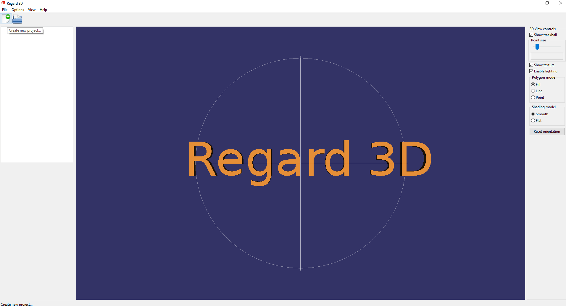
Start the software, then click on the “Create new project” button in the top left menu bar.
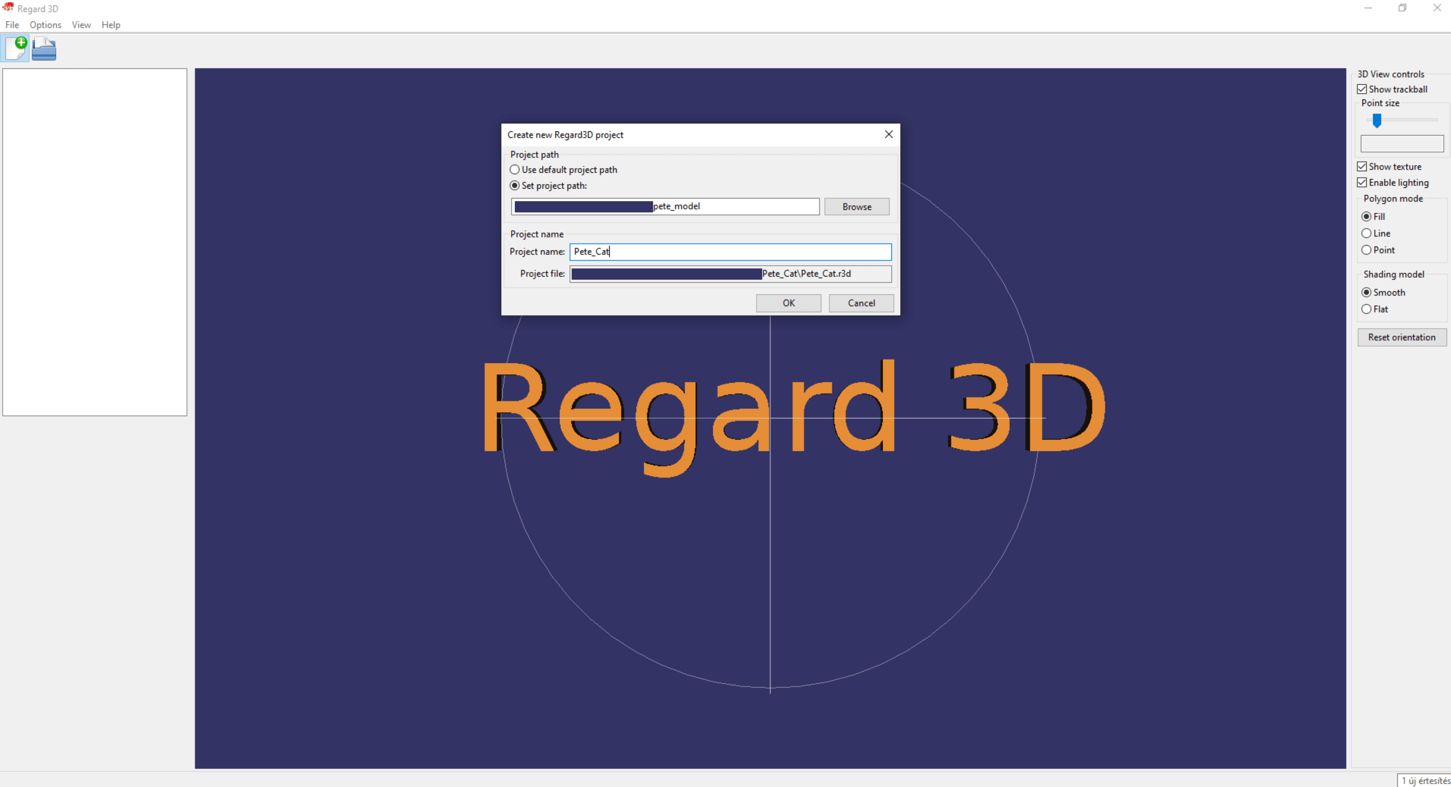
Select the location you want Regard3D to create your project file and also choose the new project’s name.
Sidenote: I think it is advisable to create a separate folder for photogrammetric processing, in which you copy the images that form the basis of the modeling into an “img” folder. Then you create the Regard3D project at the root of the folder structure, so everything will be stored in one place.
To the selected folder the software creates a “.r3d” file. The software automatically saves all partial results, changes, and deletions in the project, so you are not able to save manually.
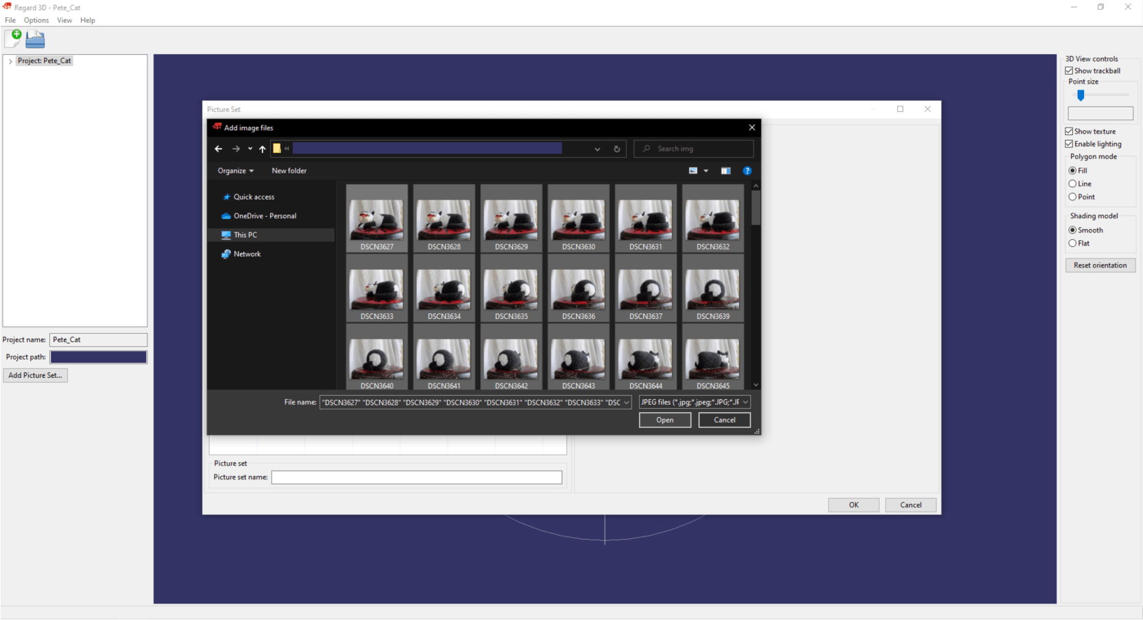
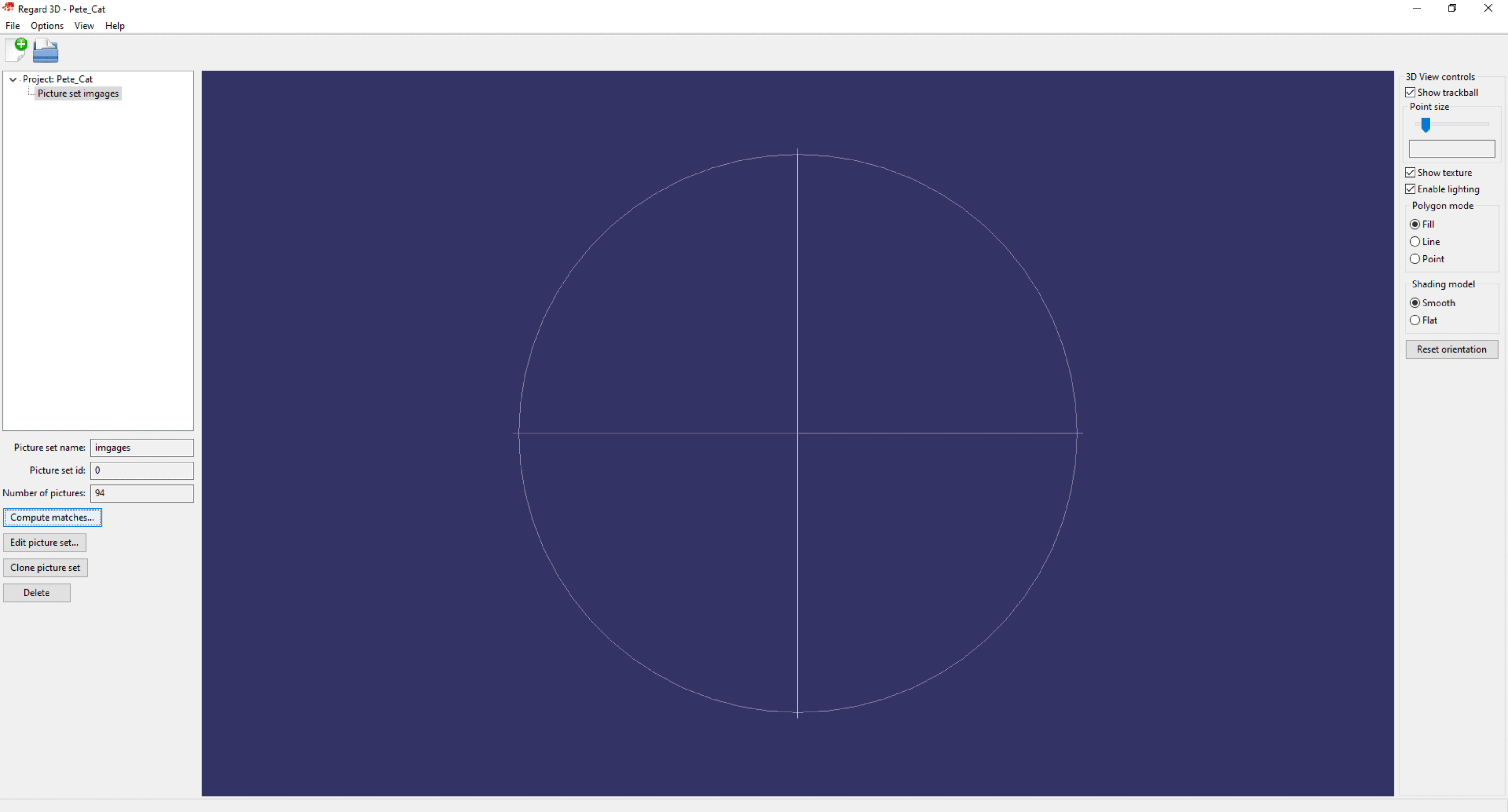
The first thing to do in the project is to add the images. You can do this with the “Add Picture Set…” button at the bottom of the left bar. The logic of Regard3D will continue to be that all further operations will be available on this interface.
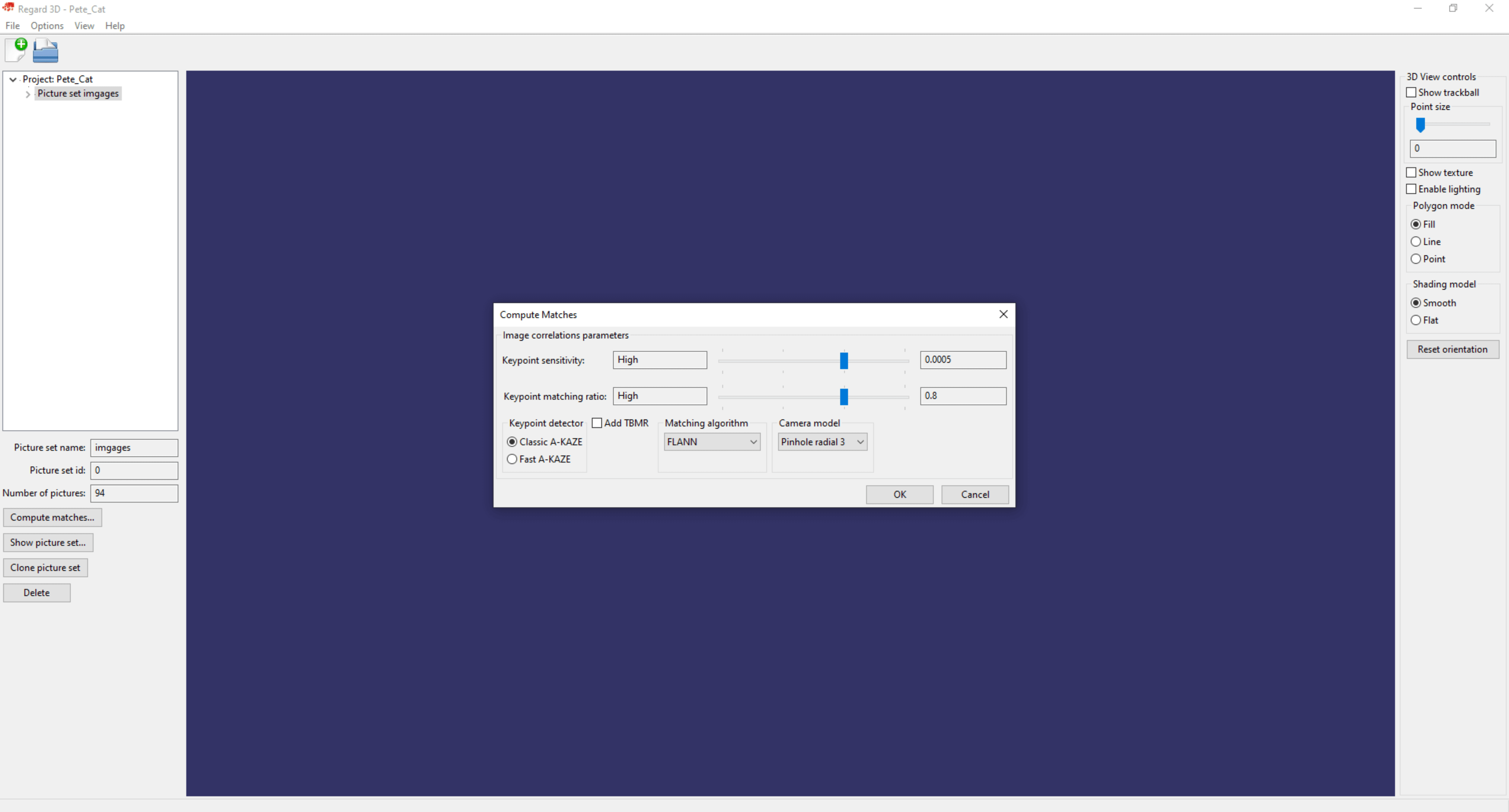
After the images are loaded, click on the “Compute matches” button. In this and the next operation, we will do the camera alignment with the images.
In the popup, I used “High” settings. If you don’t have a powerful PC or you work with a lot of images, then lower the values. Click OK.
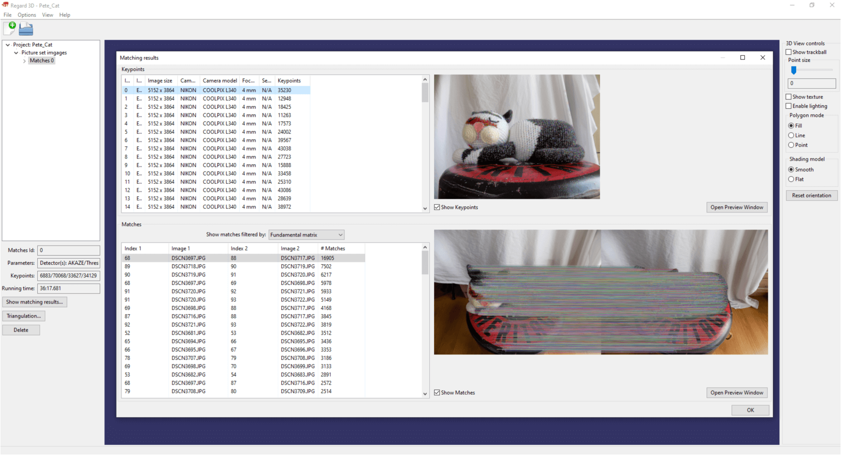
In the first step of the camera alignment the aforementioned algorithms define the mutual points of the images. These can be displayed by double-clicking on the “Matches 0” layer in the upper left bar. Here you can see the estimated mutual points if you turn on the “Show Matches” checkbox.
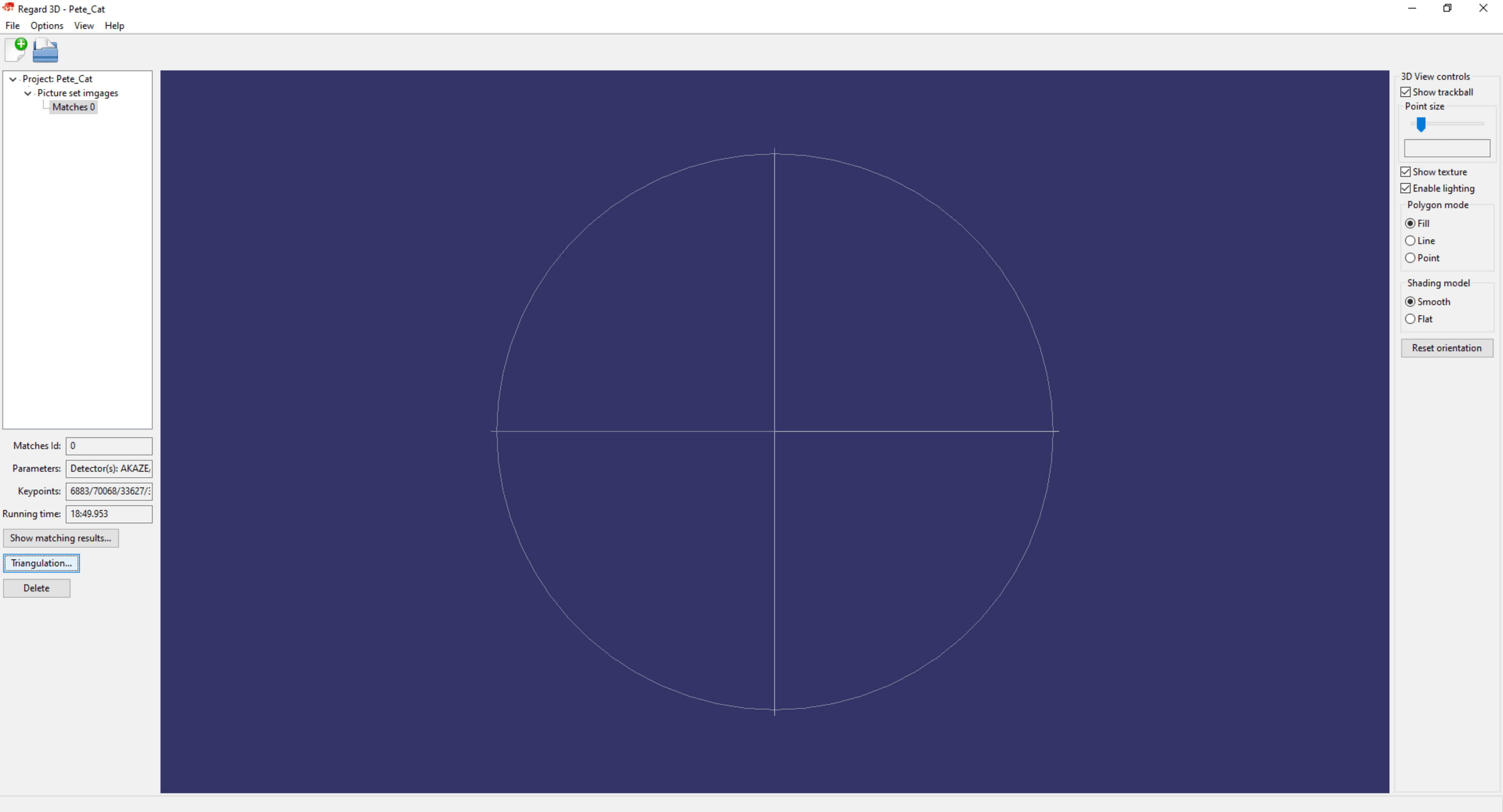
In the next step, the mutual points between the photos are placed in the three-dimensional model space. For this operation, click on the “Triangulation…” button.
I have tried different options and I achieved the best results with the settings shown in the picture.
Sidenote: If you plan to process a drone survey, you should turn on the “Use GPS information to initialize triangulation” option.
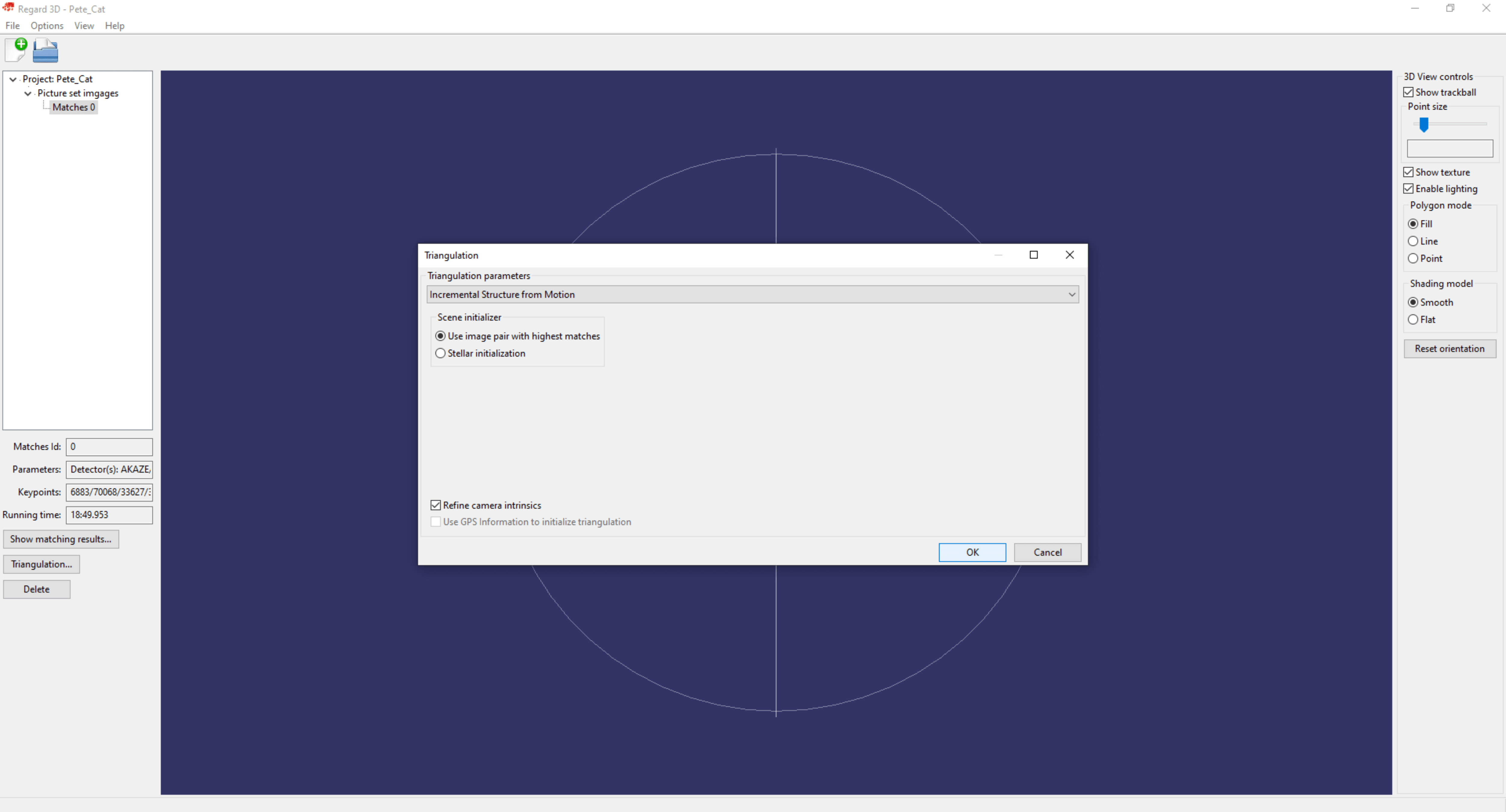
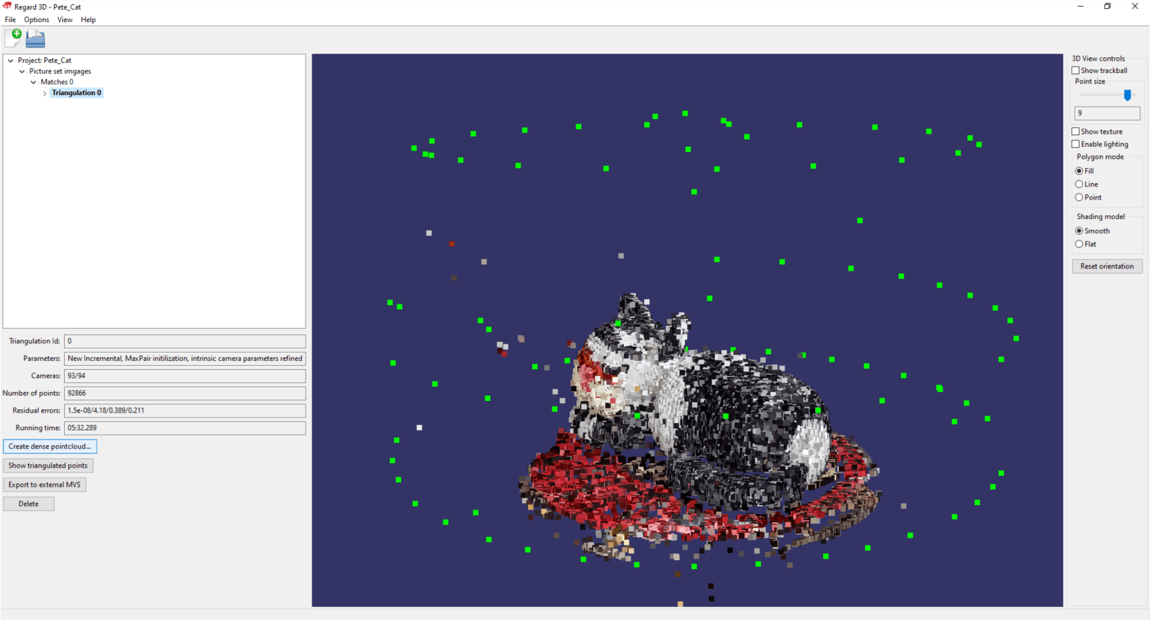
The result here will be a sparse point cloud, which is completed relatively quickly. The software was able to connect 93 out of 94 images in 5 minutes and 32 seconds. Briefly about navigating in the 3D model space… In Regard3D, you can rotate the model space by holding down the left mouse button and moving the mouse, while you can zoom with the wheels and drag the camera by holding down the right mouse button. In the appearing point cloud, you can find green points. These points show the location of the camera positions.
Sidenote: If you read our blogs regularly you might have noticed that we used the photography plan of the smaller object from article QUICK START – 3 TIPS FOR GROUND PHOTOGRAMMETRY SURVEYING.
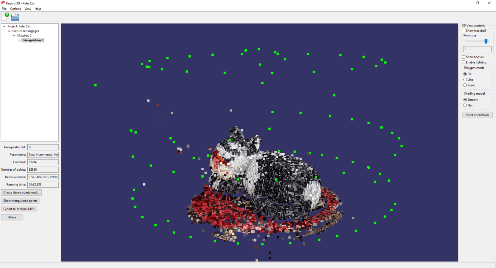
In the next step we will generate a dense point cloud, so we will discuss the second phase of photogrammetry modeling. Click on the “Create dense pointcloud…” button.
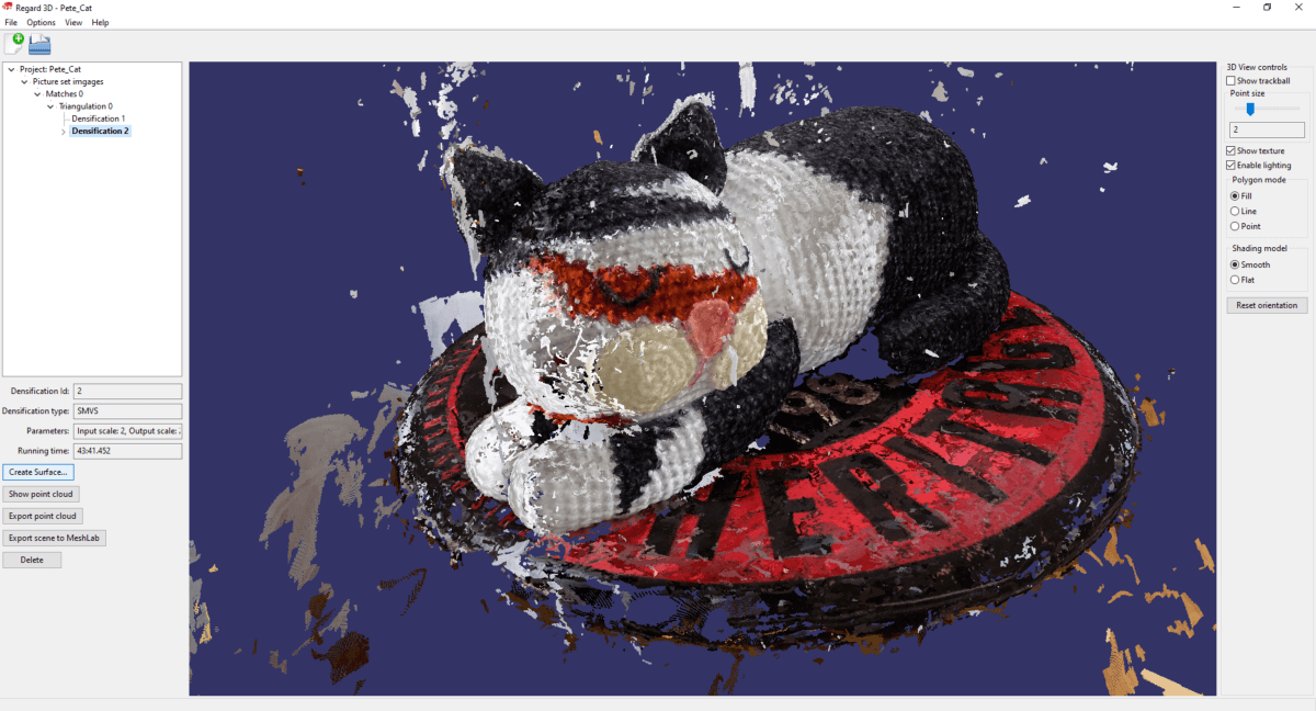
In the window that appears, I tried two different settings, the results of which are summarized in the following table.
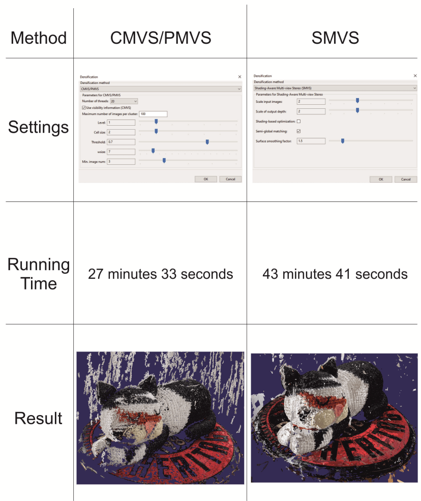
Based on the example model, I recommend the SMVS method, since the calculation time did not increase significantly, but the result was much better. There are fewer incorrectly defined data points and the point cloud is denser.
Sidenote: The settings presented and recommended in the current article do not always lead to the best quality! As many models have to be generated, that many variables have to be calculated, and in order to achieve the right results, it often happens that you have to try different settings several times. If you’d like to export the point cloud (we don’t do that in this article), click on the “Export point cloud” button.
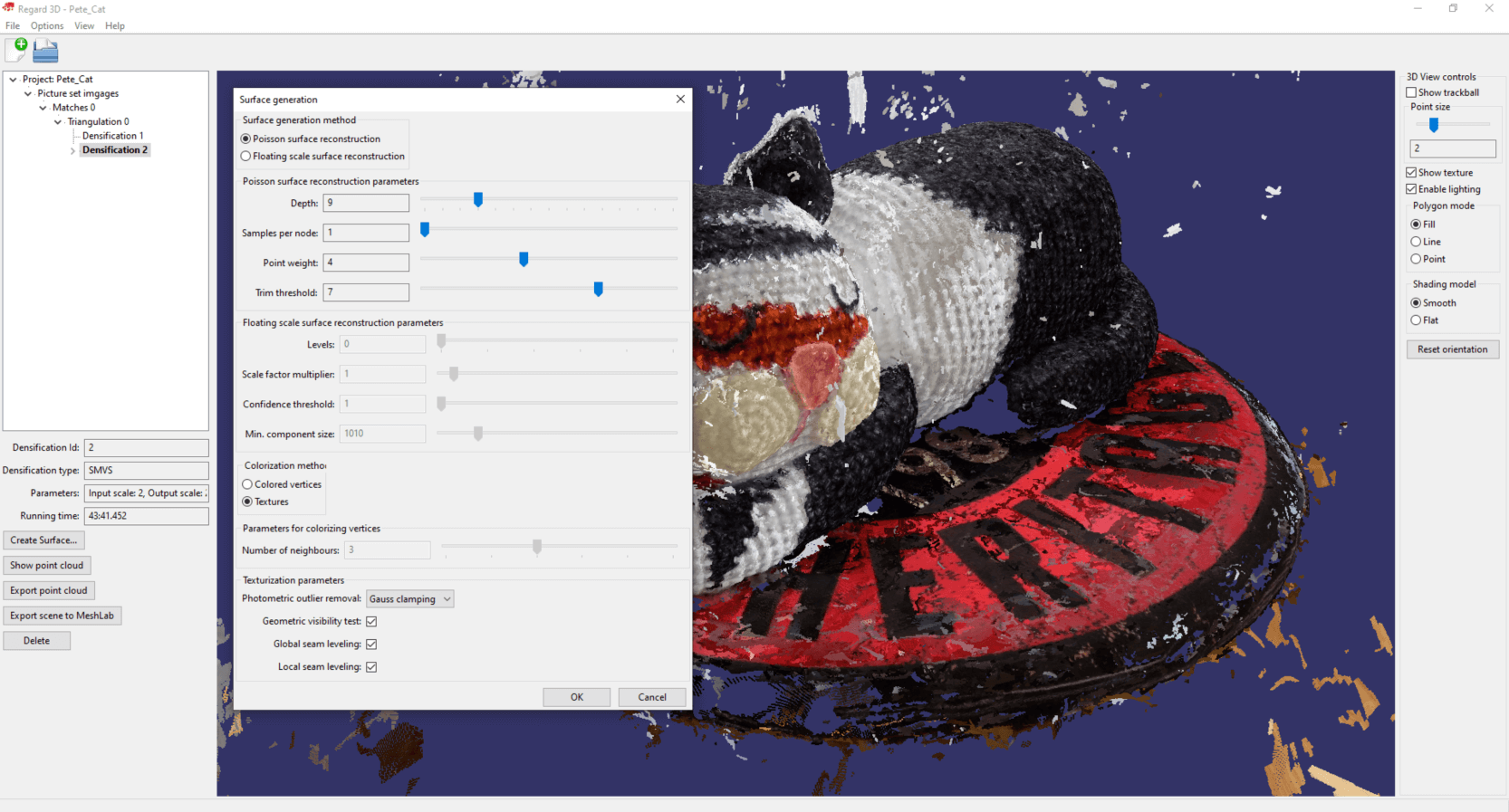
Finally create the textured 3D model based on the dense point cloud. Click on “Create Surface…”!
I achieved the best results with the following settings, but I would also like to draw your attention again to the fact that these may not be perfect in every case.
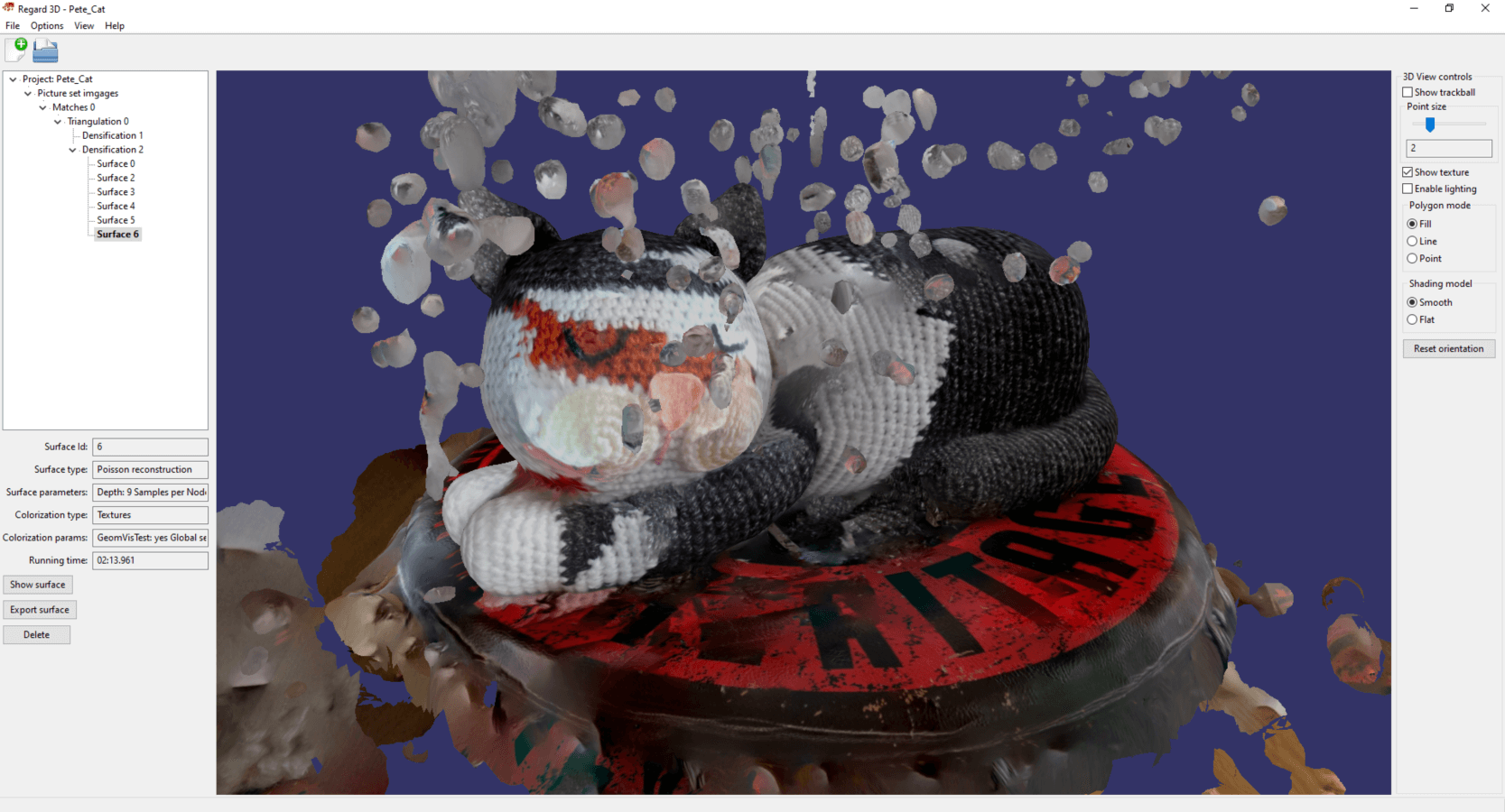
The textured model turned out to be of quite good quality, but not only the object to be modeled – Pete, the cat – was formed, but also its environment.
Press “Export surface” to export the model in “.obj” format. For this file the Regard3D will automatically generate the texture as a PNG image and will also generate a so-called “.mtl” file.
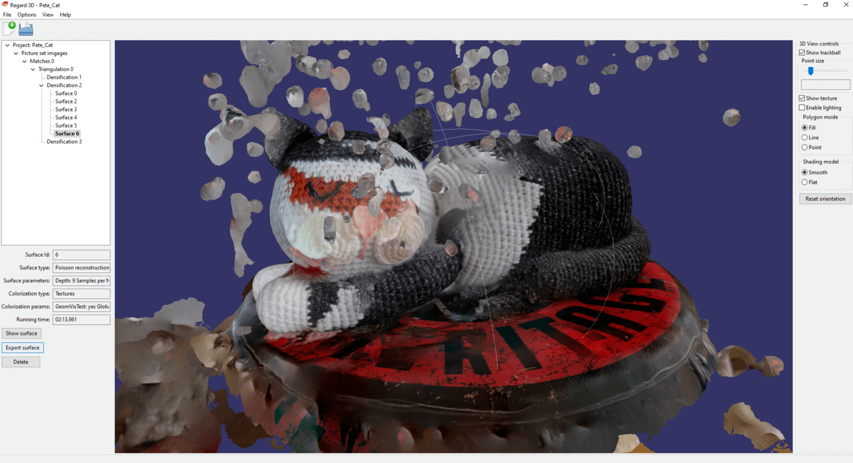
Let’s be honest… It seems that the unnecessary formations created in the cat’s environment are disturbing and Pete’s texture is not perfect either. We deal with these repairs in the next chapter!
THE 3D MODEL IS DONE…WHAT NOW?
I will show you the following fixes/modifications in this chapter:
1. Deleting unnecessary parts, cleaning the model
2. Rotating the photogrammetric model along axes
3. Creating a base for the surface model so that it can also be interpreted as a closed body
4. Creating a true-size version of the model
5. Simplifying the triangle mesh of the model
6. Fixing the texture
What will be needed during post-processing? I’m glad you asked! 🙂 We will use a free 3D modeling program called Blender. If you have installed the program and started it, you will be greeted by a start-up image, which disappears if you click somewhere next to it. Basically, I wouldn’t recommend using Blender for beginners, as the (at the same time great) program is very complicated, but I thought that this quick start could only be complete with it. Almost all navigation operations in Blender are done with the mouse wheel. By pressing it and moving the mouse, you can rotate the model space, and by pressing it while holding down the “shift” key, you can drag the model space. You can zoom in or out by scrolling with the mouse wheel.
CLEARING THE 3D MODEL
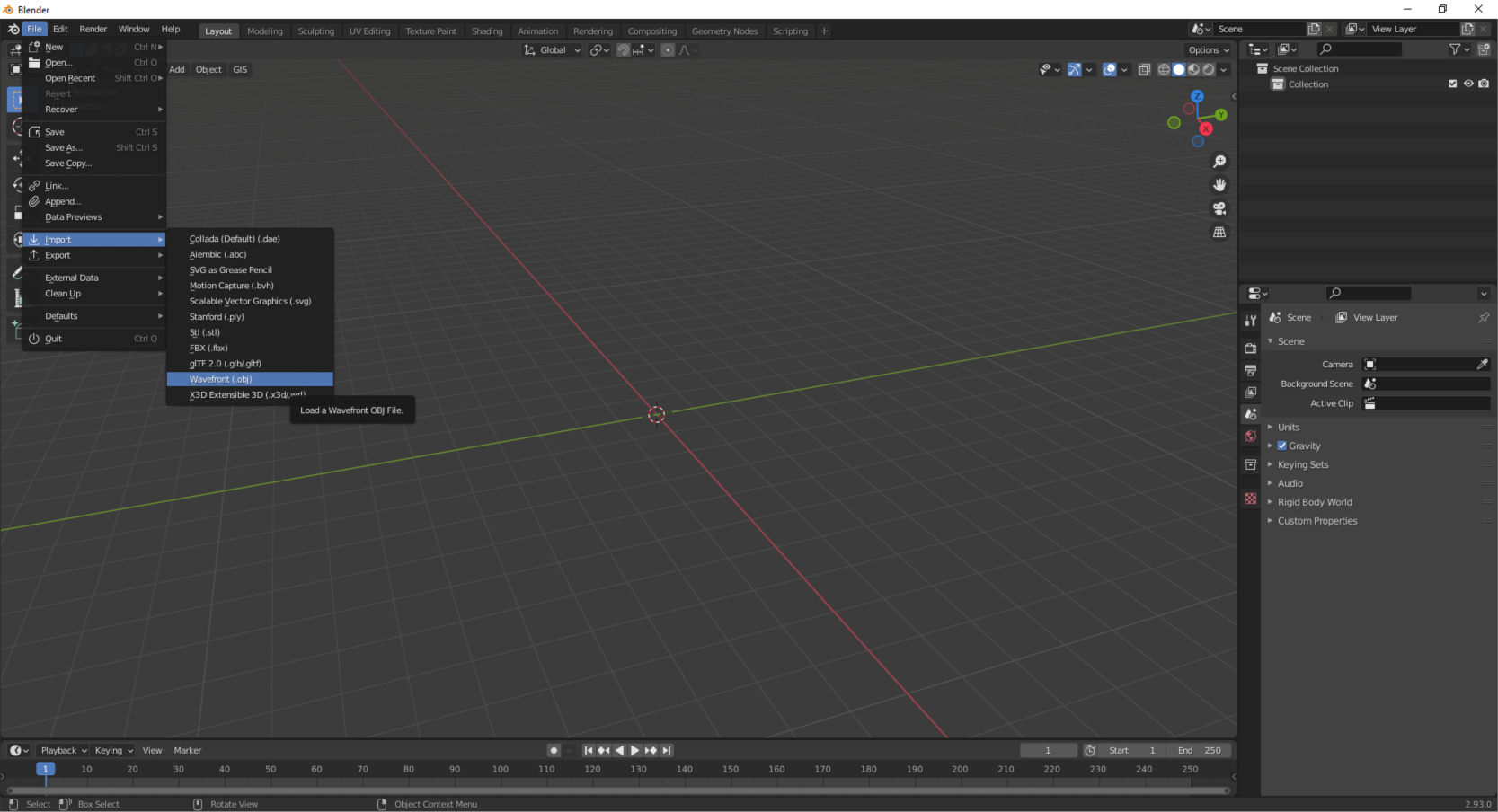
As a first step, delete everything (cube, light source and camera). Press the “A” key to select everything, then press “Delete” to delete the items. Import the model saved from Regard3D! You can find this under the File/Import, then click on the “Wavefront (.obj)” option.
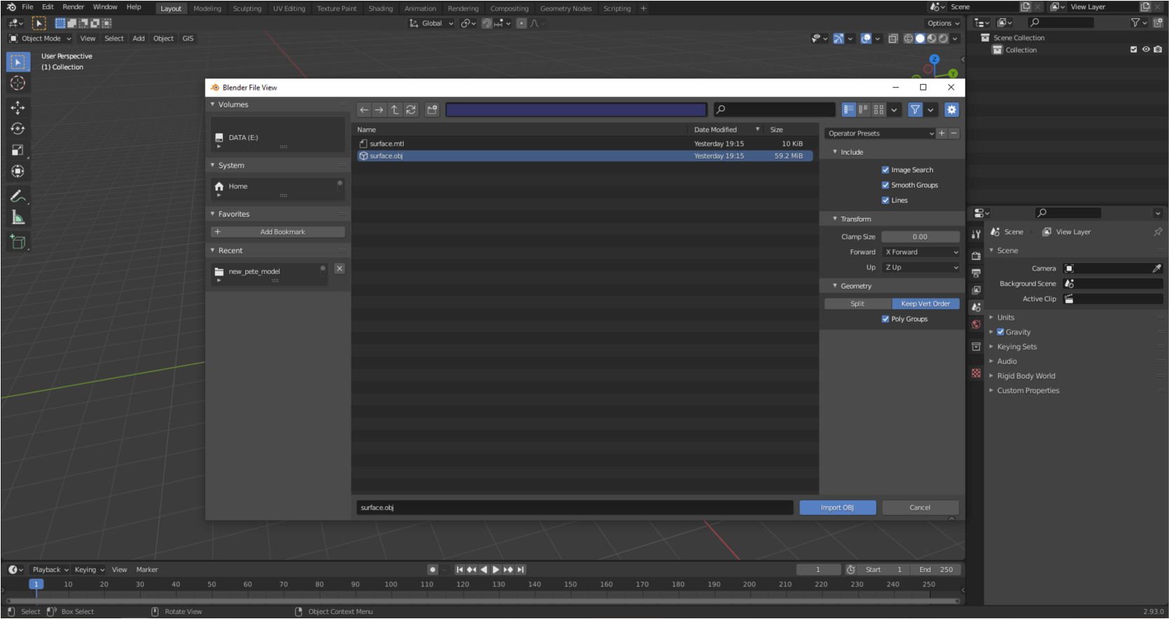
Browse the saved file, but don’t press the “Import OBJ” button yet. Before that, we need to set the value of “Forward” to “X Forward” and “Up” to “Z Up” in the right bar under the “Transform” tab. Next, under “Geometry” select the “Keep Vert Order” option, then check the “Poly Groups” box. You can now import the model! 🙂
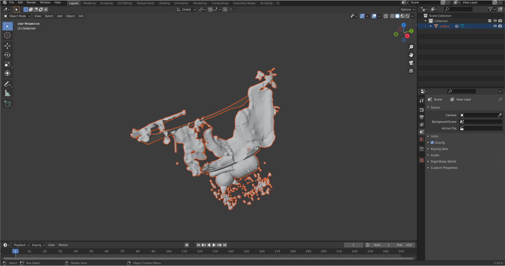
After a few seconds, you will see that the model has appeared in the layer tree on the right, but it cannot be seen in the model space. This is because the size of the model is too small compared to the displayed space. If you press “.” key on the numpad (View/Frame Selected, if there is no numpad), it will automatically zoom in on the model.
Sidenote: I suggest you save the Blender project file often, avoiding possible data loss. The save option can be found under the “File” menu.
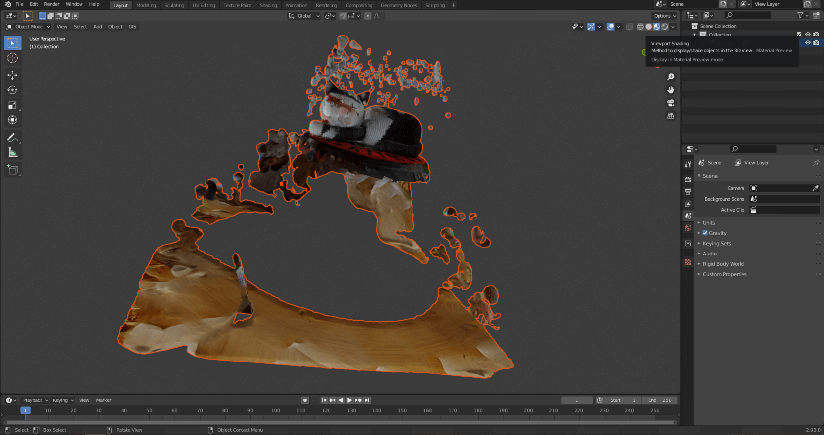
You can display the texture by clicking on “Material Preview” in the upper right corner of the model space.
Start editing and delete the unnecessary parts. Left-click on the model to select it then press the “Tab” button. We just entered the editing mode.
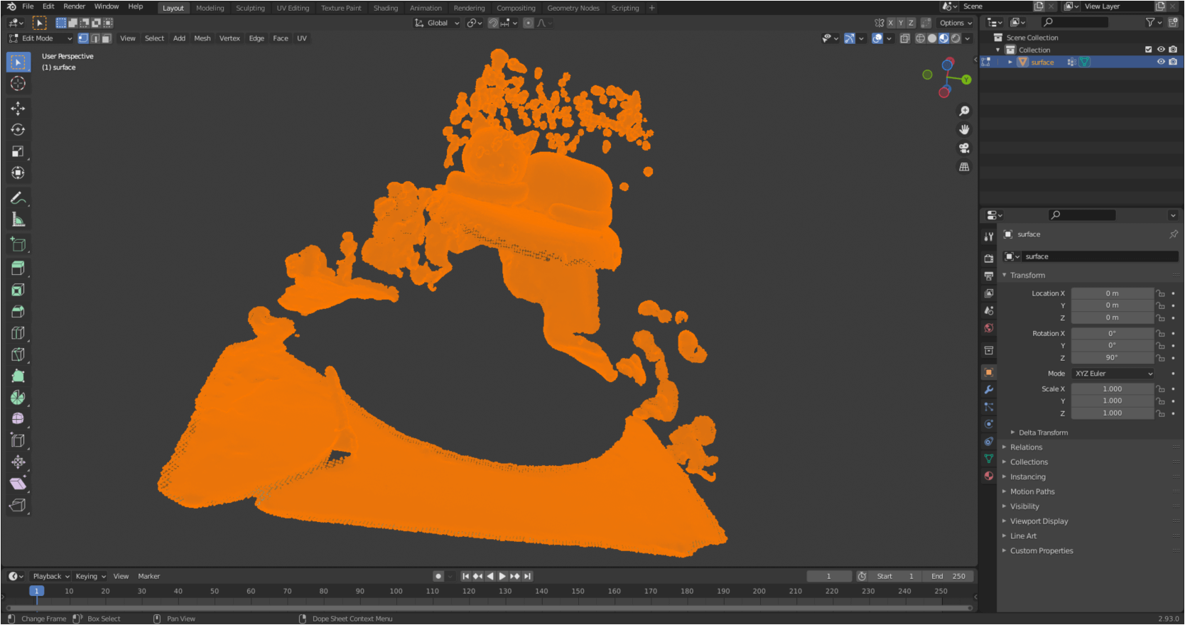
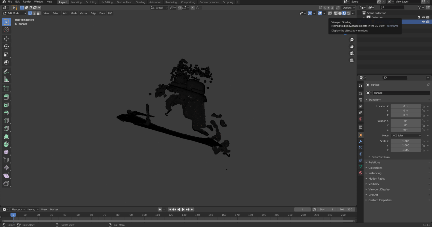
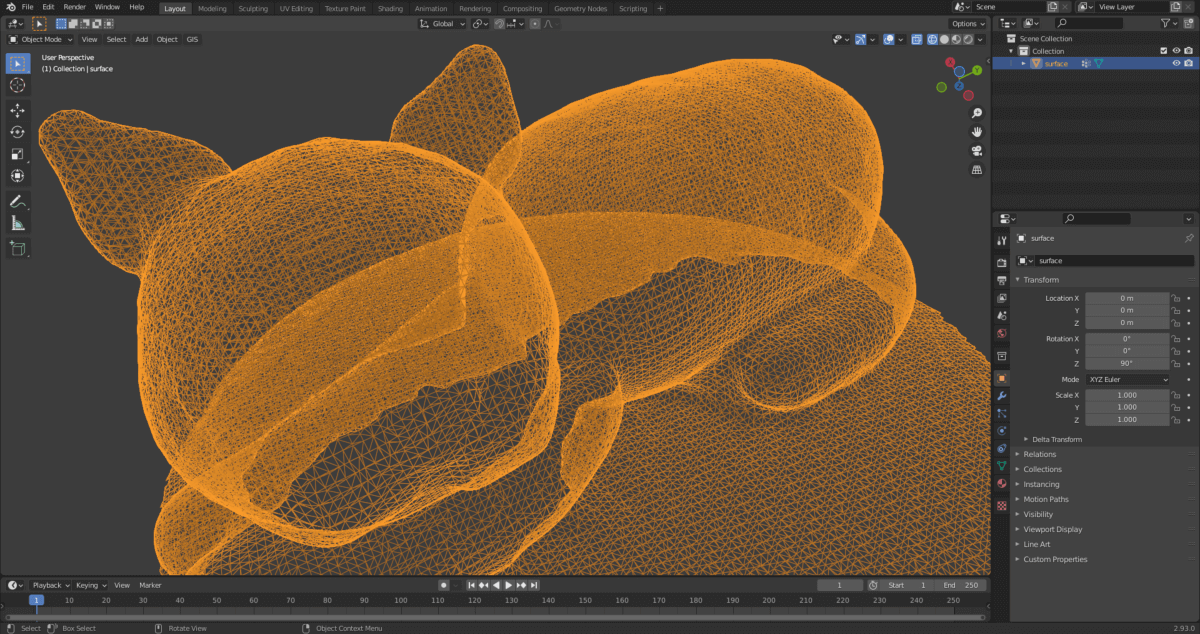
You can see that the mesh that makes up the model is extremely dense, and we’ll do something with that to optimize usability and file size. Left-click in model space to deselect. Where you first selected the appearance of the textured model, now switch to “Wireframe”. This view will be beneficial because what you select will not only apply to the parts visible from the current camera position, but also to those which are currently covered.
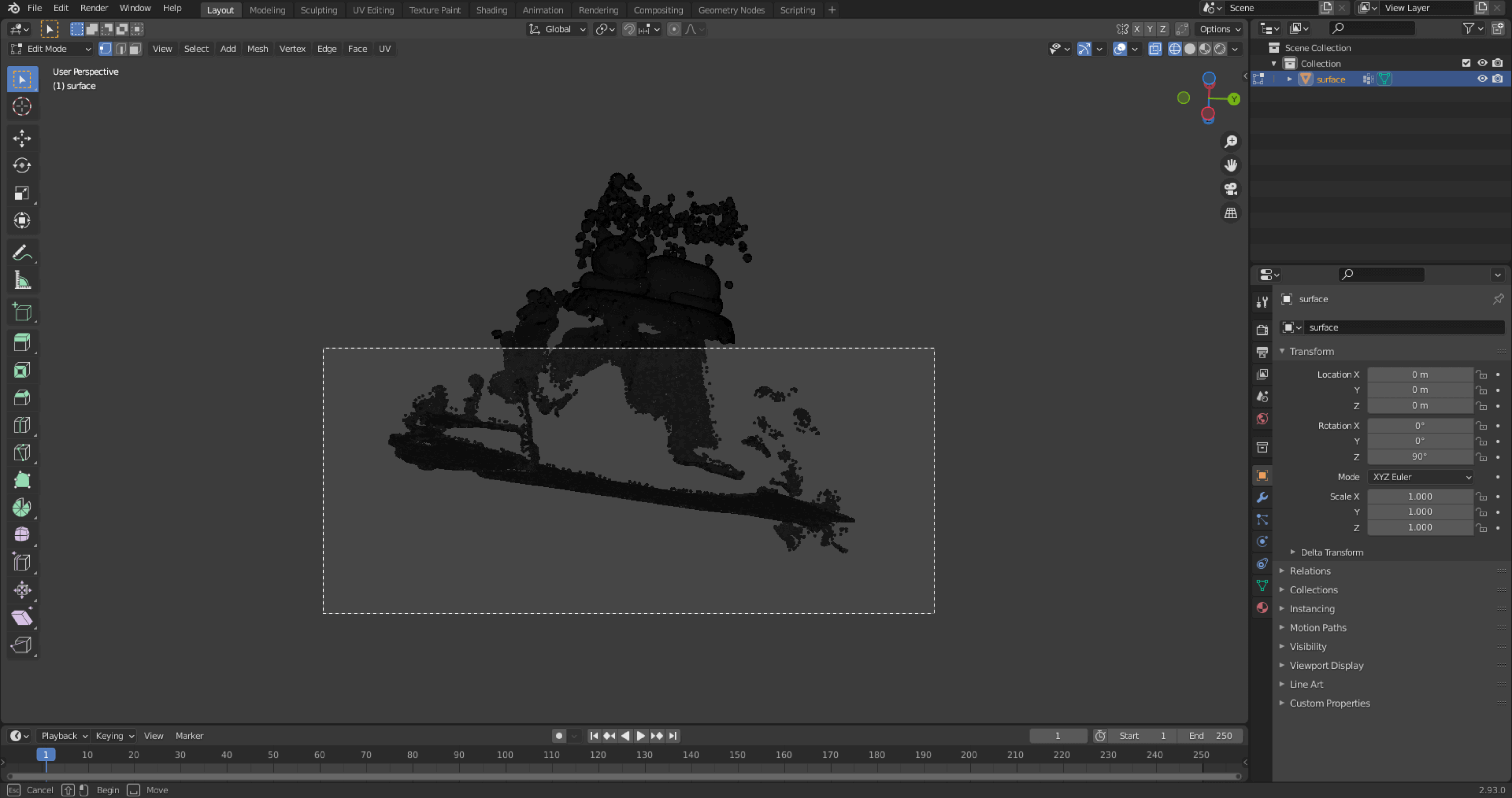
Select a part of the model by holding down the left mouse button.
Then delete the unnecessary parts. Press the “Delete” key, then click on the “Vertices” local menu item.
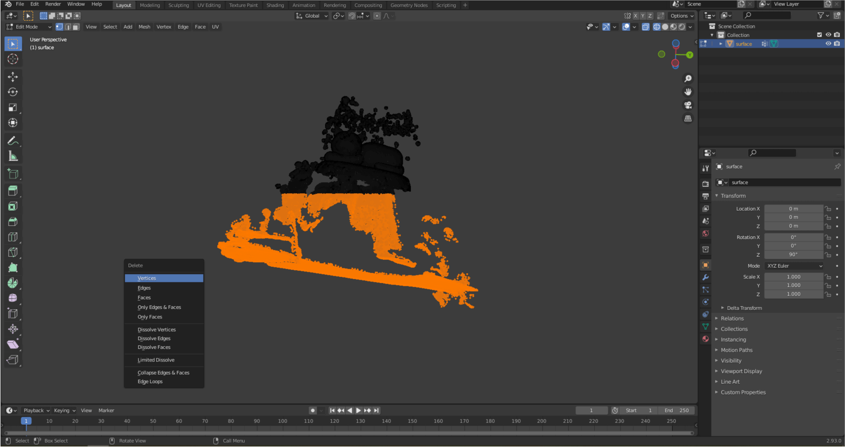
Clear all the unnecessary parts from the model. Rotate the model space if needed. If you‘re done, press “Tab” again to exit editing mode.
ROTATING THE 3D MODEL
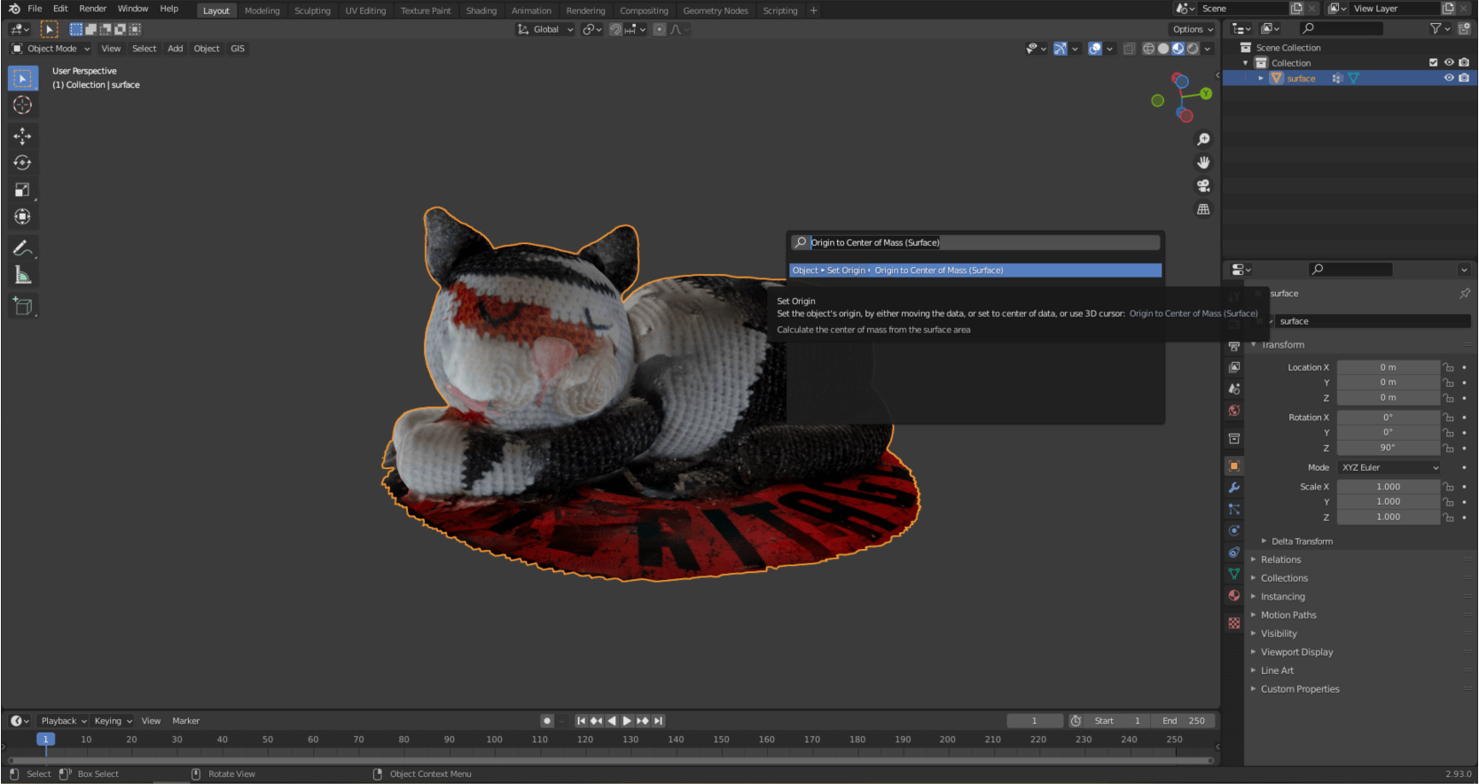
In the next step we will place the model of Pete to the center of the model space to make the following steps easier. Press the “F3” key to bring up a search window. Enter “Origin to Center of Mass (Surface)” and select the first option.
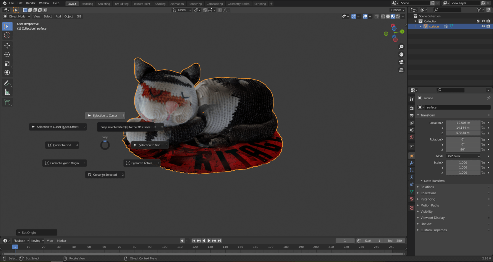
By pressing the “Shift” and “S” keys at the same time, you can call up a context menu, here choose the “Selection to Cursor” command.
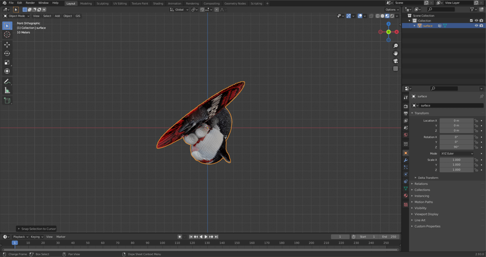
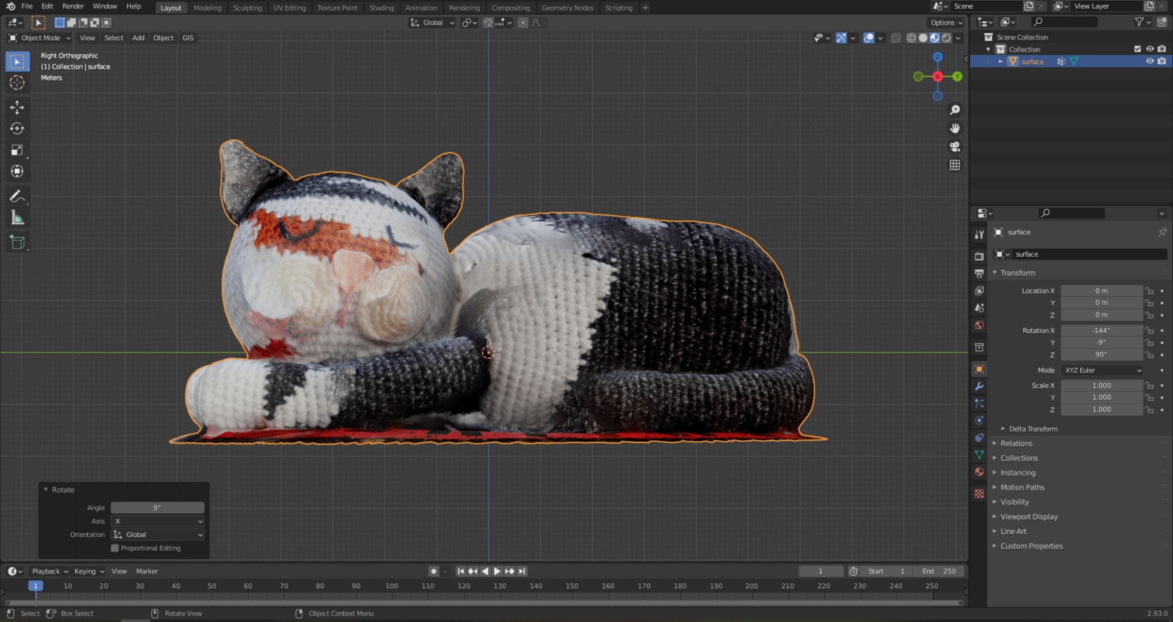
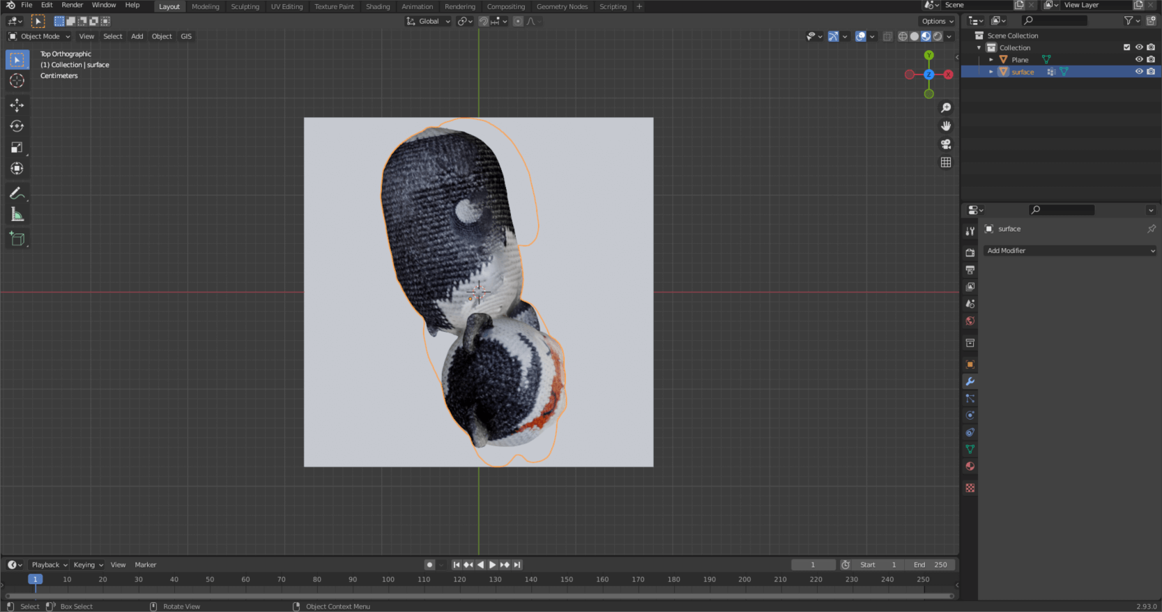
This moves Pete to the origin of the model space, so he disappears from your screen. Don’t worry, our cat is not lost! Press “.” on the numpad, so you can now see the model. Press “5” and then “1” on the numpad. With the former, we switch from the previous perspective view to orthographic, while with the latter we switch to a side view. From here you can see that Pete is a little upset. 🙂 Let’s fix it!
Press the “R” key to rotate the model (not the model space!). Hit “Y” as well, this will only rotate the cat along the Y axis. Repeat this operation on the X axis as well. You can do this by pressing “3” on the numpad, then pressing “R” and finally “X” in the program based on the previous example.
Sidenote: If you want to raise the model to the base plane (in the next picture it is marked by the green line), then press “G” to move the model. Then press “Z” to move it along the Z axis.
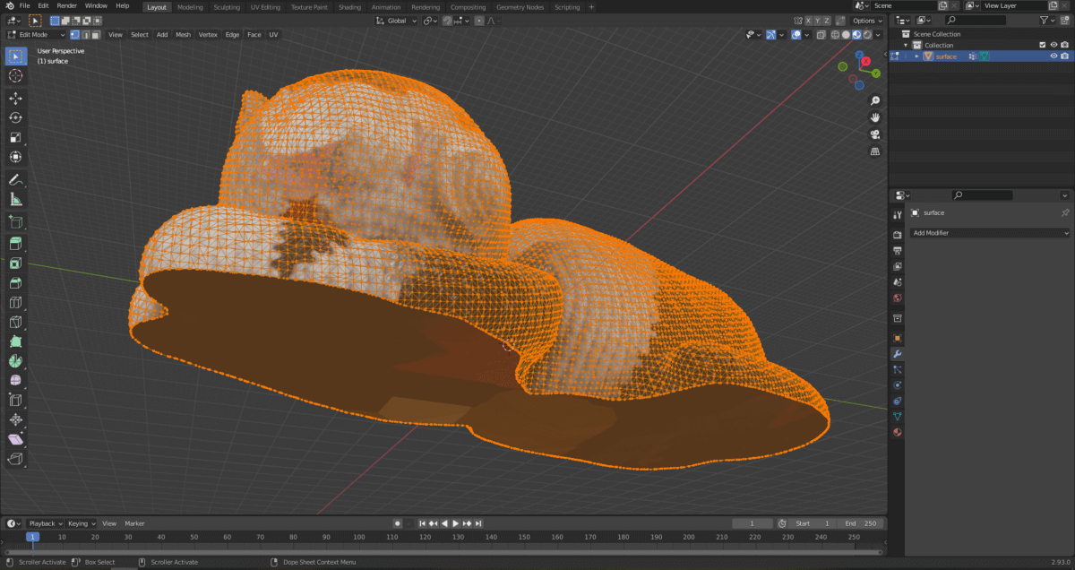
SHAPING THE BASE OF THE SURFACE
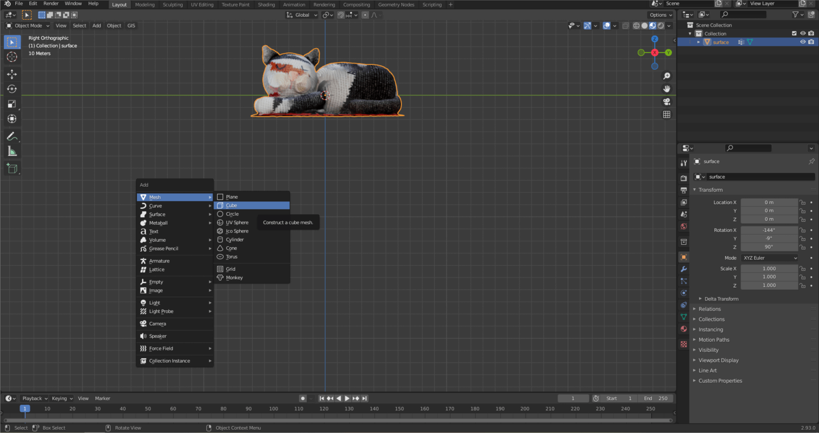
If we rotate the model space, it can be seen that the lower part of Pete is not closed and the surface on which I placed Pete has been formed too. Let’s fix this too! Press “Shift + A” to create a new geometry. Select “Cube” from the “Mesh” menu.
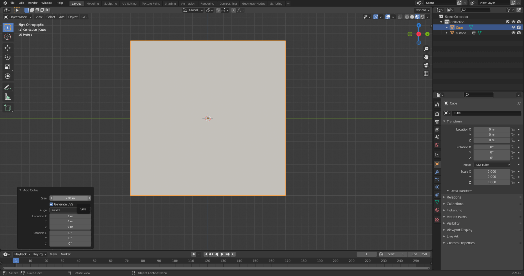
Increase the size of the cube enough to cover the model.
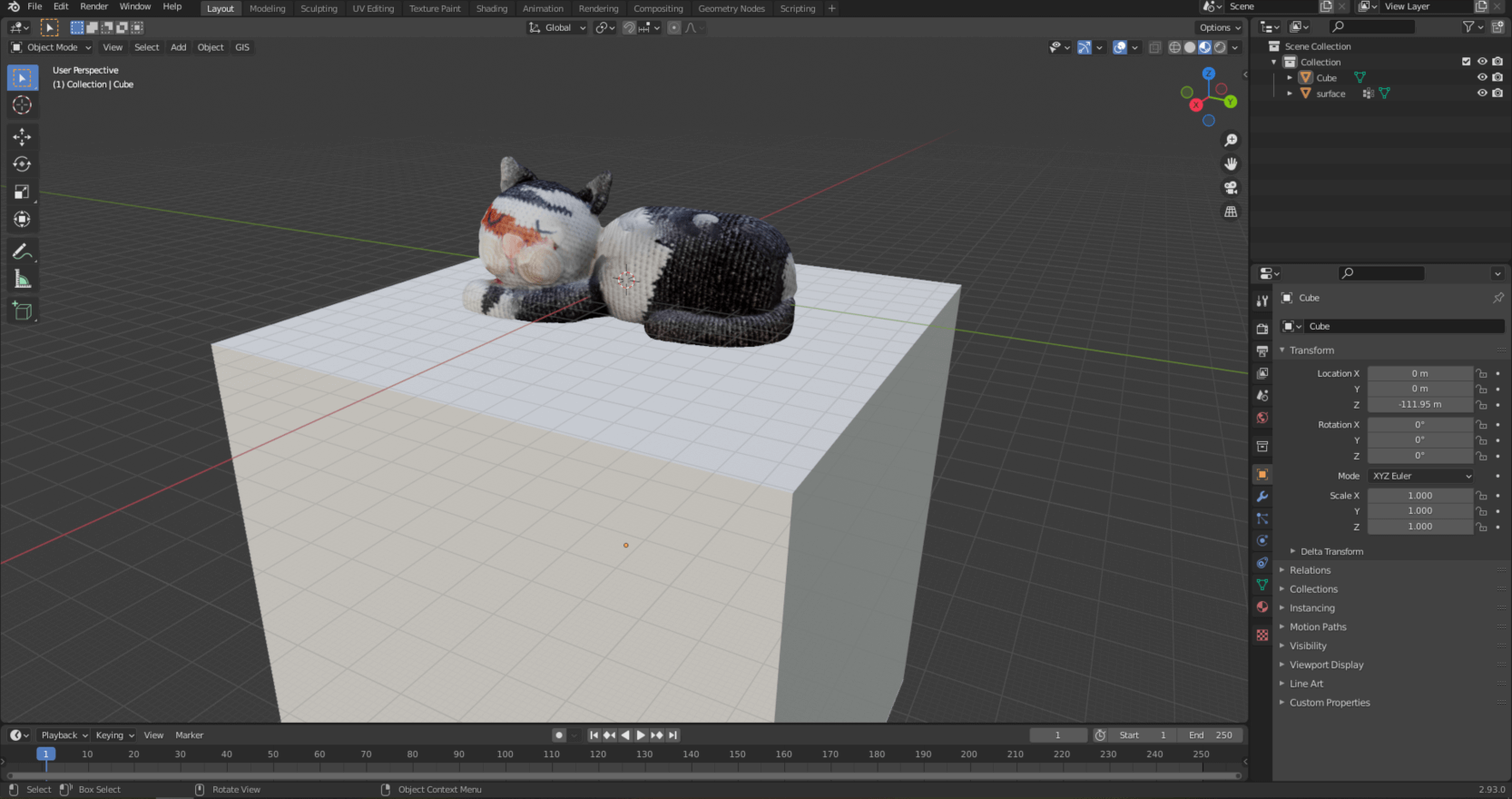
Then move the cube down by pressing the familiar “G” and then “Z” keys. This gave Pete a nice base plane.
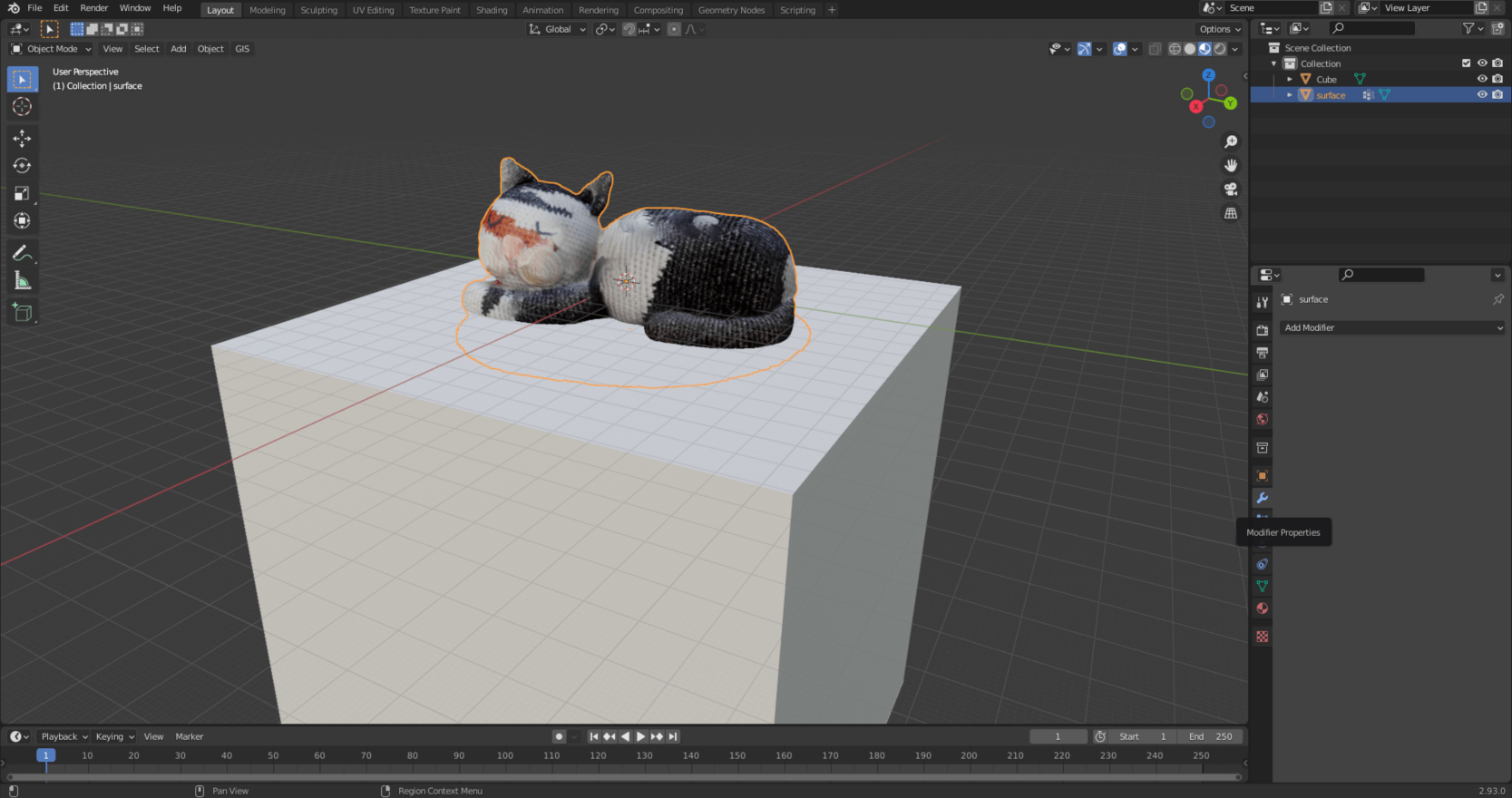
This is only apparent, so let’s merge the cat and those parts of the cube which intersects the cat. Select Pete, then select the wrench-shaped icon from the small icon bar on the right, i.e., “Modifier Properties”.
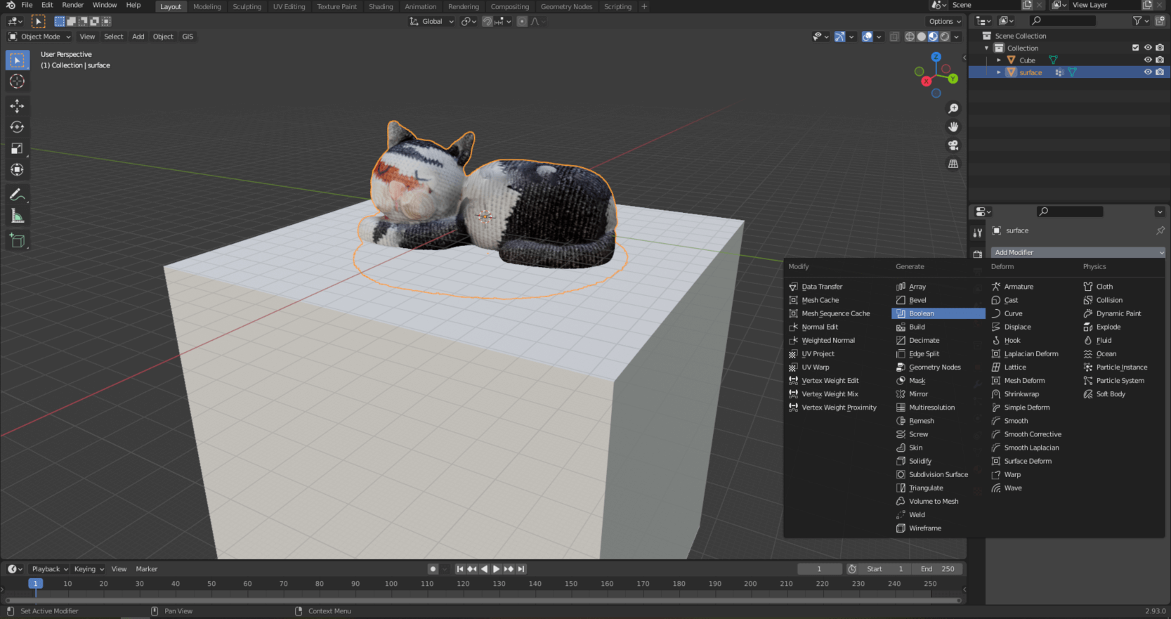
Select “Boolean”.
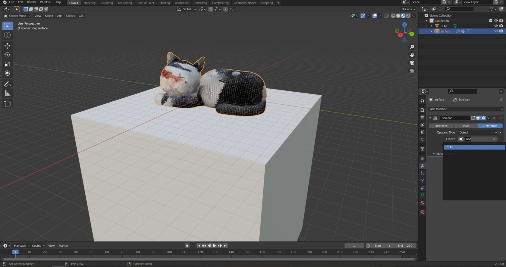
Under “Difference” set “Cube”.
Accept the changes as shown in the following image. You can then delete the cube; it will no longer be needed.
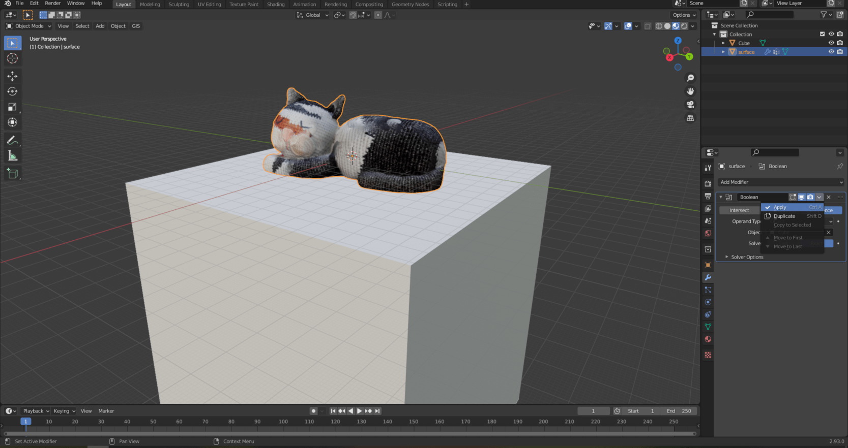
This makes Pete’s model a closed geometry.
MAKING THE MODEL TRUE-SIZE
Unfortunately, the model does not have real dimensions, because it has a length of about 120 meters, but poor Pete does not live on such big feet, He is only 36 cm long. We will fix this discrepancy during the next operation! The easiest way is to use “Shift + A” to create a “Plane” geometry, the length of which will be 36 cm. Then select Pete’s model and press the “S” key and use the mouse to scale the model so that it is as long as the created plane. The easiest way to do this is to press the “7” button on the numpad and zoom in on Pete from the top view. You may need to shift the model in one direction or another with the “G” command.
Sidenote: Remember! The best practice is to georeference the model either with a tape measure or with geographic coordinates. The presented scaling operation is a quick solution, but not accurate!
SIMPLIFYING THE MESH
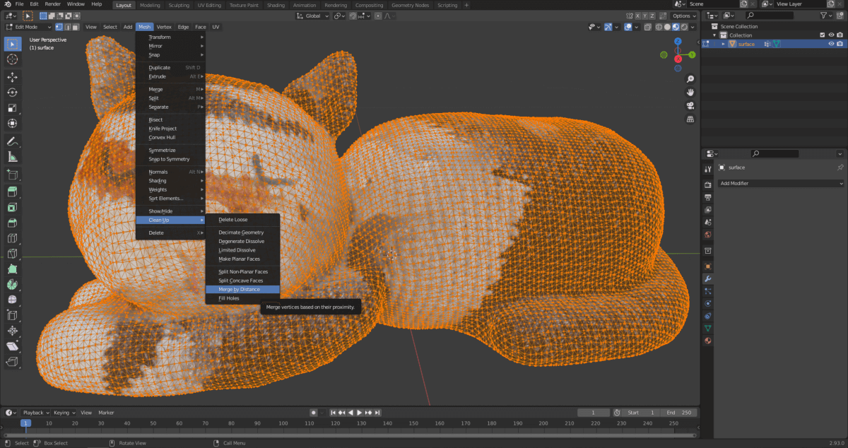
It’s often useful to use a simplified version of a model instead of the original one. The edits and computationally demanding processes become more manageable and each method becomes less resource-demanding. With this, we can also achieve a smaller file size. Recalculating the mesh is called “remeshing”.
Select the model and press “Tab” to enter the editing mode. Then select “Mesh” from the floating buttons at the top of the model space, then select “Merge by Distance” from the “Clean Up” menu.
The mesh elements that make up Pete’s model were significantly simplified, but the geometry was not significantly distorted after setting 0.85 m.
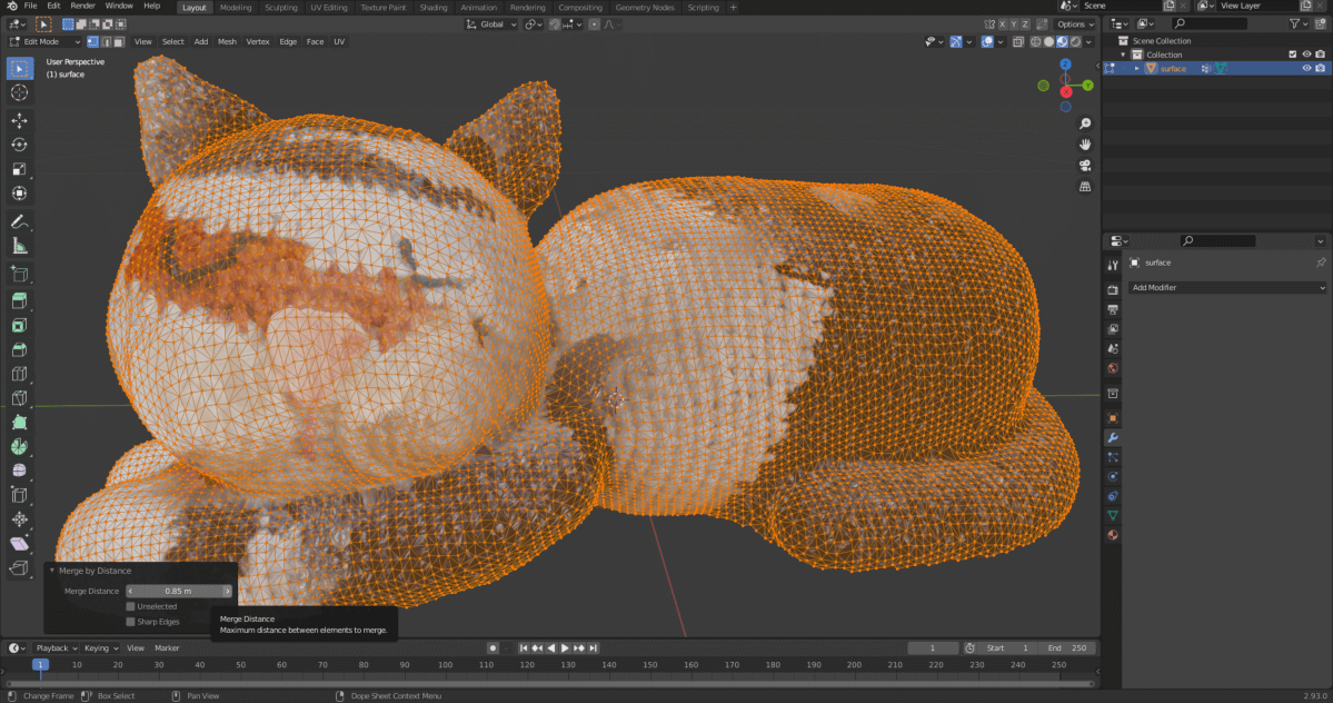
Sidenote: For more complex geometry, this simple procedure does not always give satisfactory results. If you want to delve into the topic, be sure to watch this video.
CORRECTION OF THE MODEL’S TEXTURE
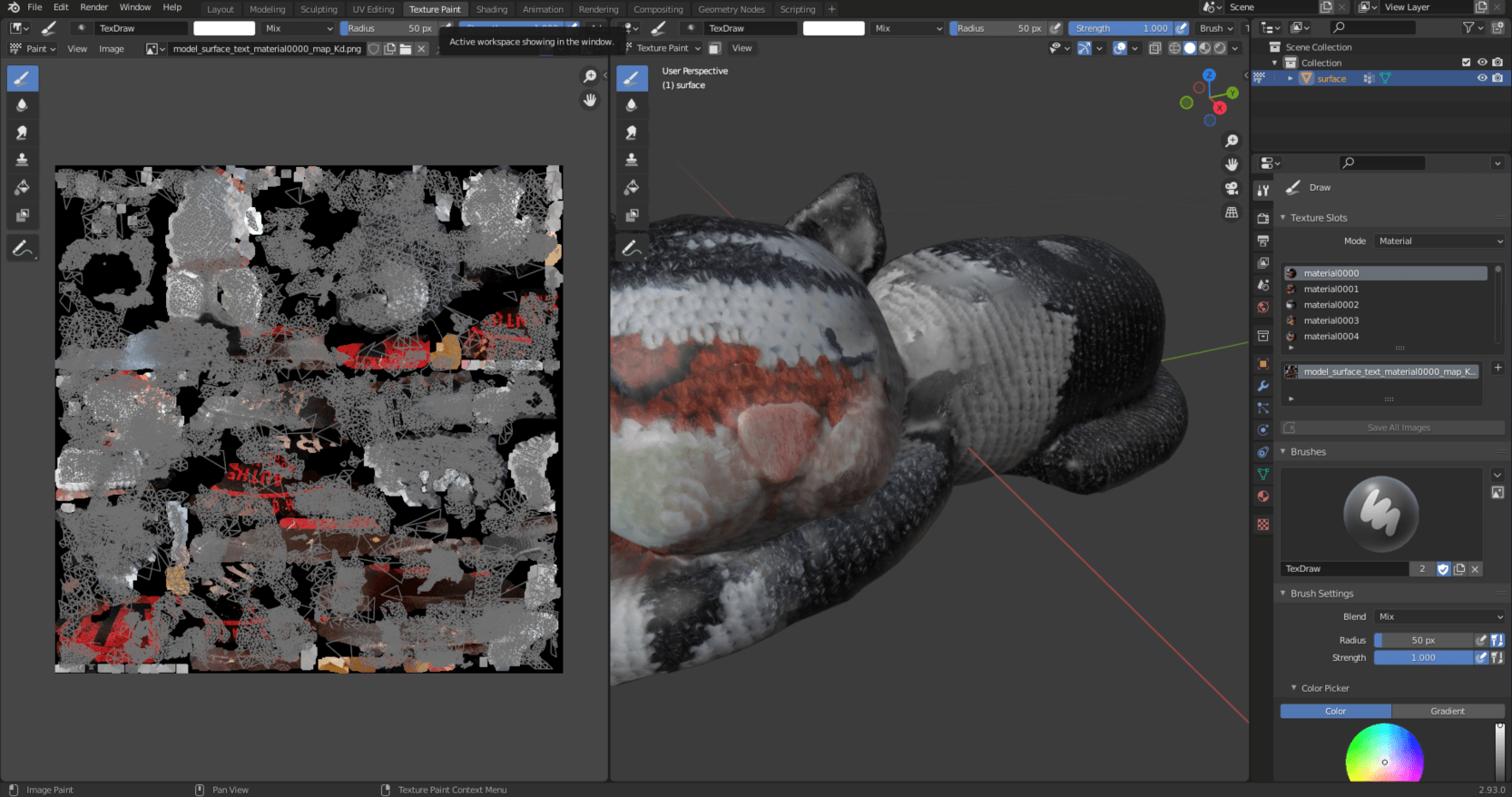
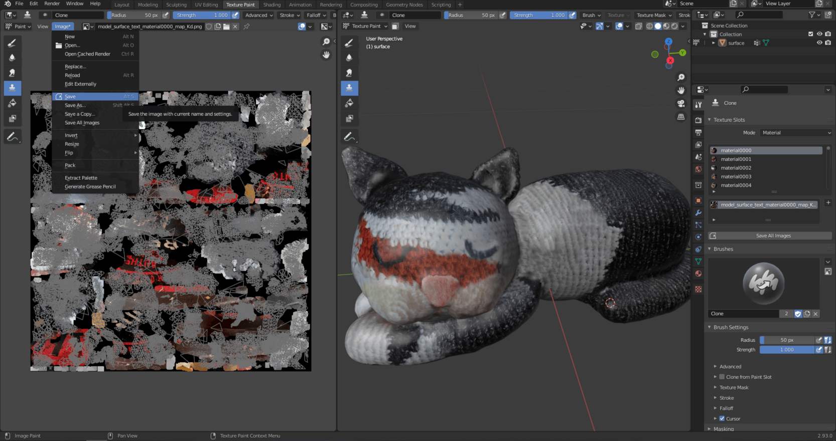
There are several cases – as we see with Pete’s model – that the texture is not perfect and we have to improve it manually. Fortunately, this is also available in Blender. Select “Texture Paint” from the top menu bar.
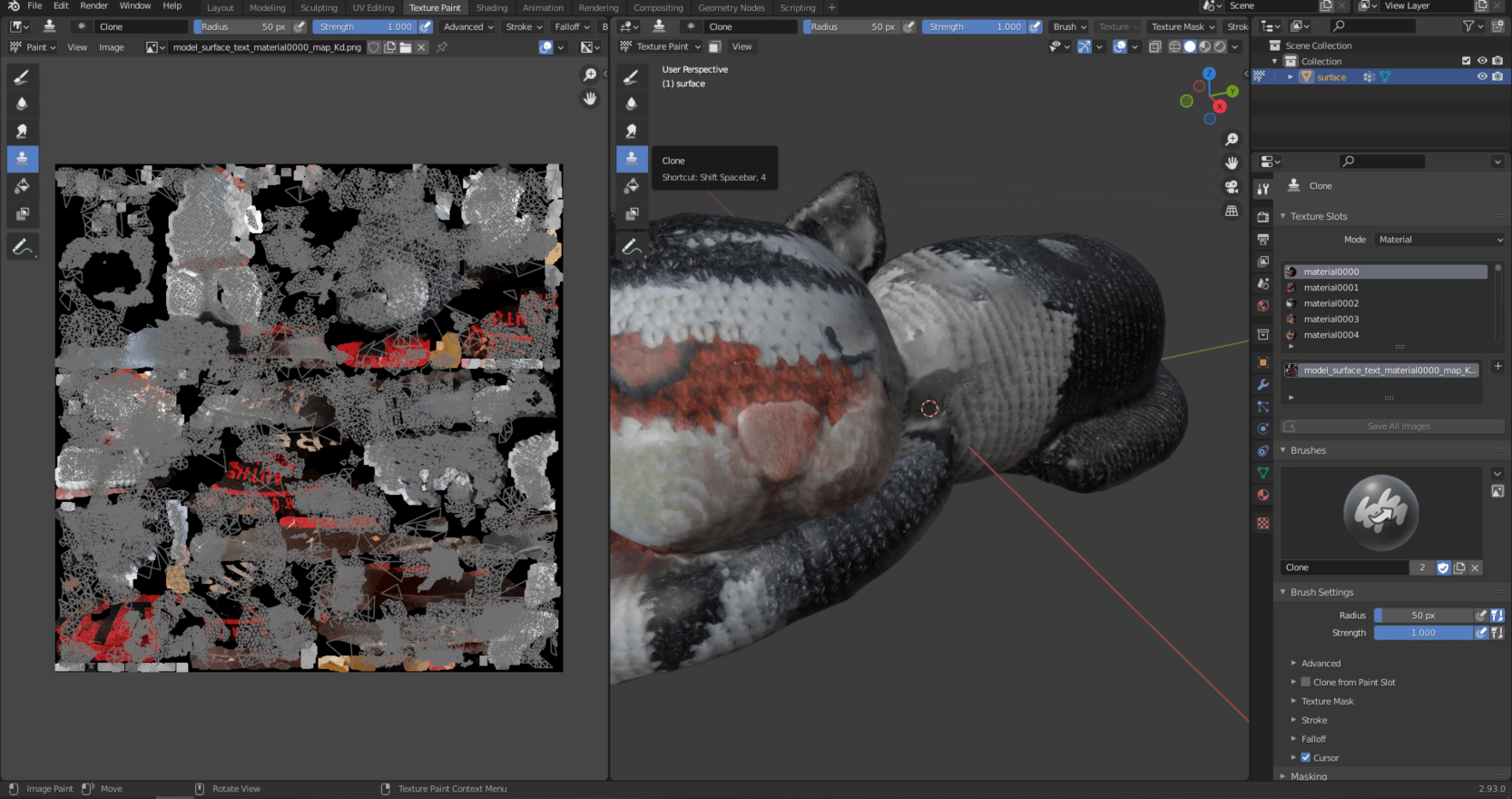
Select “Clone” from the floating menu on the left that appears in the model space.
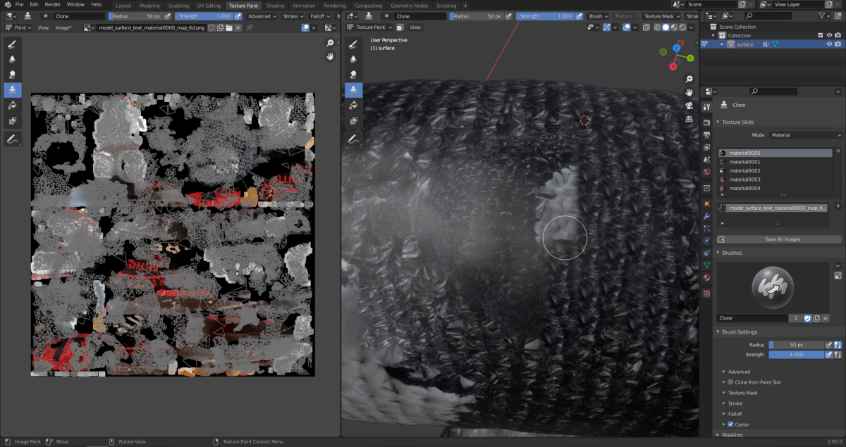
By zooming in on the model and selecting a specific point of it, you can copy a texture element with “Shift + right mouse button”. The texture of the area marked with the cursor can be projected onto another part if you keep the left mouse button pressed and move the mouse. You can see that this removes the white texture element on Pete’s back.
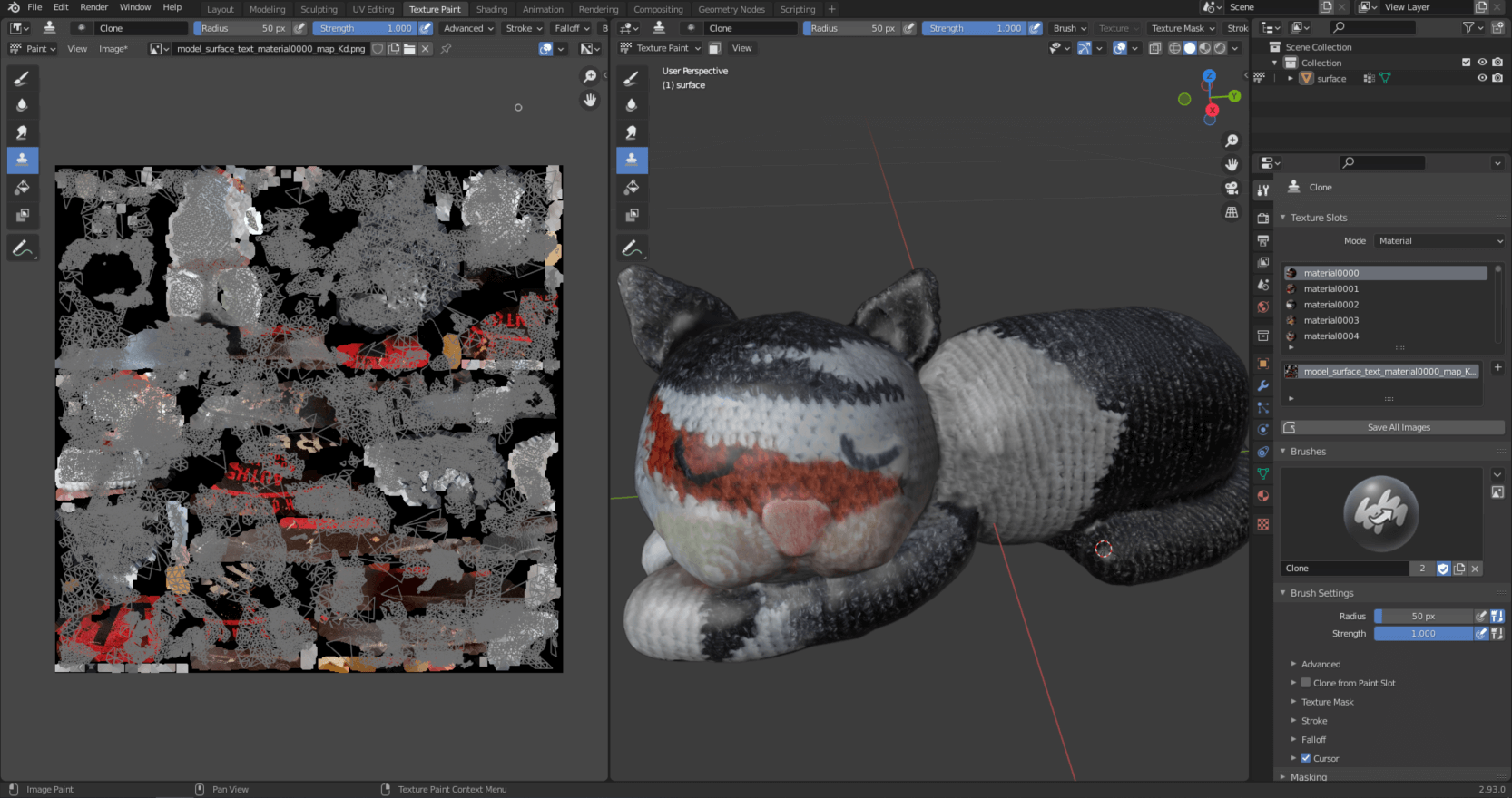
Of course, you can freely navigate in the model space while improving the texture. If you would like to increase the size or strength of the brush, you can adjust the “Radius” and “Strength” parameters in the upper part of any viewport. The end result of the “Texture Paint” process will be a 3D model that reflects reality much better.
Be sure to save the image that is the basis of the texture separately when you are done with the texture modifications.
Sidenote: If you want to learn more about photogrammetric model correction options and texture improvement, I recommend this video.
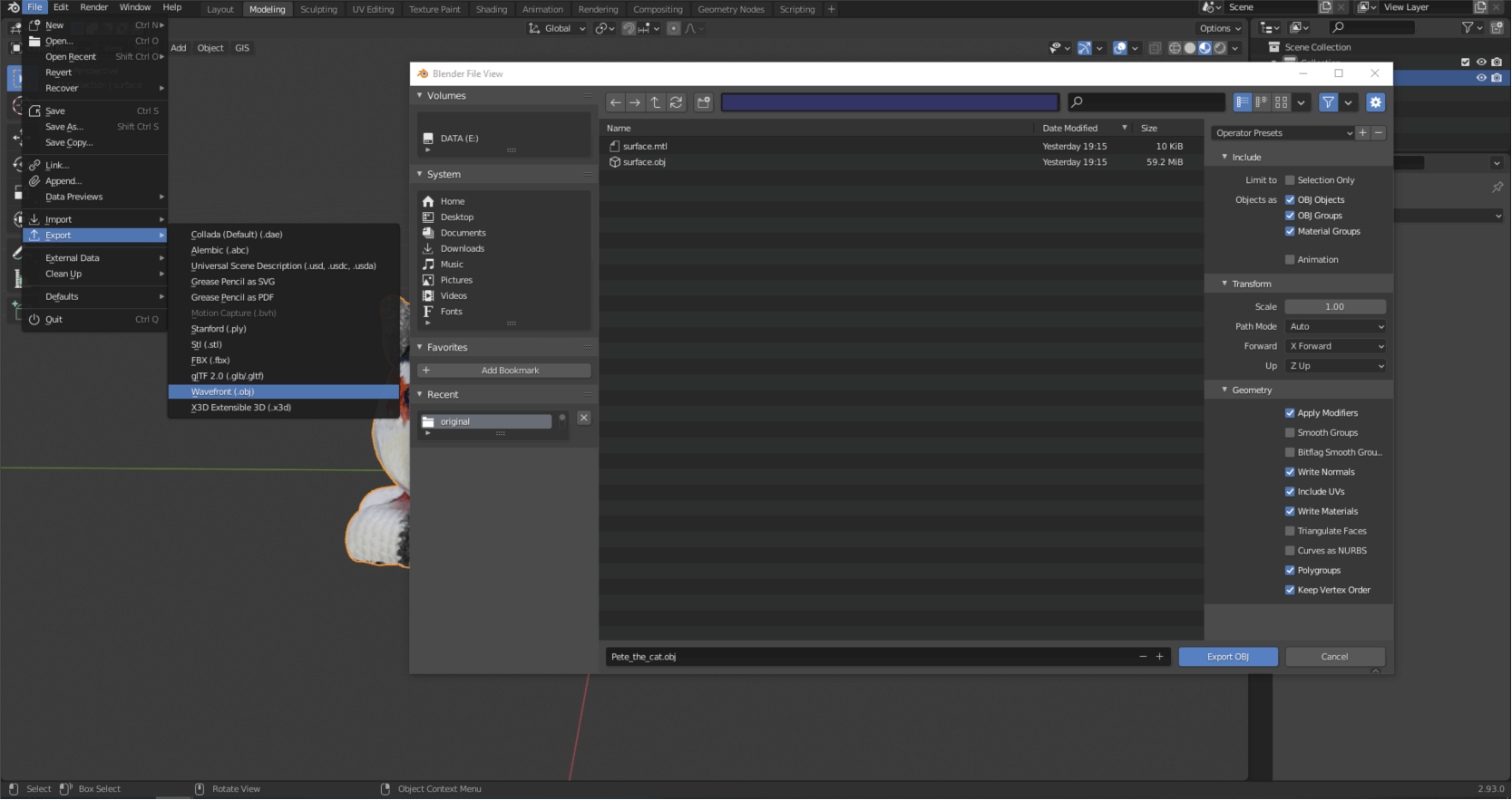
At the end of the 3D model from photo action line, the created model can be saved in different formats, for example “.obj” format. This is under the File/Export/Wavefront (.obj) menu. I recommend the following settings when saving the 3D model.
WHAT WILL BE THE NEXT QUICK START ABOUT?
In the next quick start, I’ll show you how to take photos with a drone for photogrammetry purposes.
The output files of the 3D model from photos method (photogrammetry) can be large point clouds, orthomosaics, digital elevation models (DEM) and 3D models. These can be difficult to share with the client and colleagues. It is strongly recommended to use the SurveyTransfer data sharing software! For more information, visit the website of the software manufacturer by clicking HERE.
If you really liked what you read, you can share it with your friends.
Did you like what you read? Do you want to read similar ones?