
3D model can be created by processing the results of photogrammetry and laser scanning. There are many software for post-processing 3D model, but Blender has one of the largest toolkits and community support. Blender is free, open source software, so feel free to try it out! Basically, it was not invented for the analysis and post-processing 3D model for geoinformatics purposes, but for 3D artists and animators. However, many Blender plugins support the use of 3D geoinformatics, with which we can work in a geographic coordinate system or just calculate volume and surface. We have already presented Blender in several articles on our blog.
In the current article, you will learn the following 3D model manipulation tricks:
- Blender: Automatic detection of geometric errors in the 3D model;
- Blender: from a 3D surface model to a solid – this is how you calculate volume and surface;
- From Blender to CAD: 3D model for finite element simulation calculations.
The operations presented in this article are based on the existence of good geometry from properly executed data collection and processing! If it’s about photogrammetry, you might be interested in these previous articles:
- A MINDSET FOR SUCCESSFUL AERIAL PHOTOGRAMMETRY SURVEY PROJECTS
- 5 TIPS TO FOLLOW FOR EXCELLENT TERRAIN AWARENESS PHOTOGRAMMETRY
- QUICK START – 3 TIPS FOR GROUND PHOTOGRAMMETRY SURVEYING
- QUICK START – 3 STEPS TO A DRONE PHOTOGRAMMETRY FLIGHT PLAN
- GPS, GNSS, RTK, PPK – POSITIONING METHODS IN AERIAL PHOTOGRAMMETRY
We have already written about Blender and its functions:
- FOR WHAT AND HOW YOU CAN USE GEOSPATIAL DATA?
- QUICK START – HOW TO CREATE 3D MODELS FROM DIGITAL PHOTOS
- GIS-BASED BUILDING MOTION ANALYSIS STEP-BY-STEP
Sidenote: In our current article, we will not go into detail about the navigation in Blender and the basic software structure. This basic information can be found in our articles mentioned above!
BLENDER: AUTOMATIC DETECTION OF GEOMETRIC ERRORS OF THE 3D MODEL
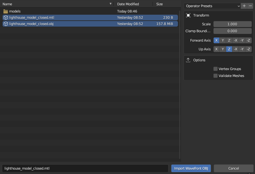
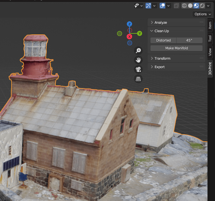
Once you have installed and launched Blender, import the 3D model. Many formats are supported by the software and even more extensions are available through plugins.
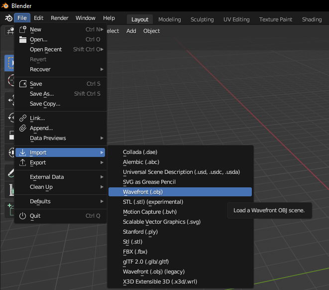
During the import, make sure to correctly set the axis directions that affect the orientation of the 3D model!
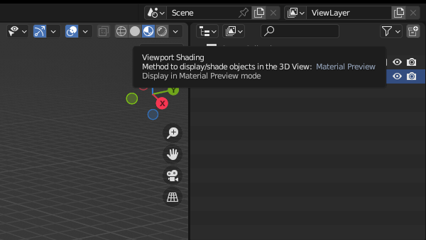
Hopefully the 3D model has appeared in the model space. If not, you can zoom in with the “.” key on the Numpad. You can also view the textured 3D model by clicking on the “Viewport shading” icon in the top right corner.
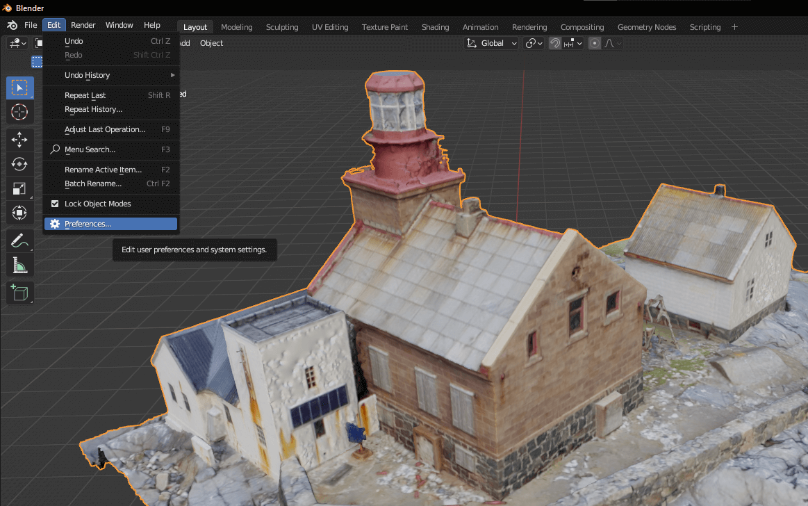
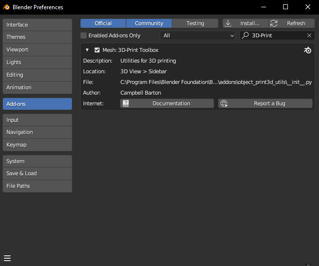
Once you ascertain that yes, this is the same 3D model – the data of which was created with such painstaking work in the field that you’ve aged 10 years by the end of the processing – and you created it yourself, install a plugin! Select “Edit/Preferences…” from the top menu bar of Blender.
If you start typing “3D-Print” in the search bar on the right, Blender will automatically list the plugin called “3D-Print Toolbox”. Check the box next to the plugin and the installation is complete!
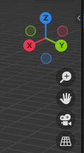
In Blender’s 3D model space, in the top right corner, next to the arrows indicating the directions, you will find a barely visible little arrow, click on it, you will find the plugin’s tools here.
Switch to the “3D-Print” tab, this is what we will use in this tutorial 🙂
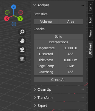
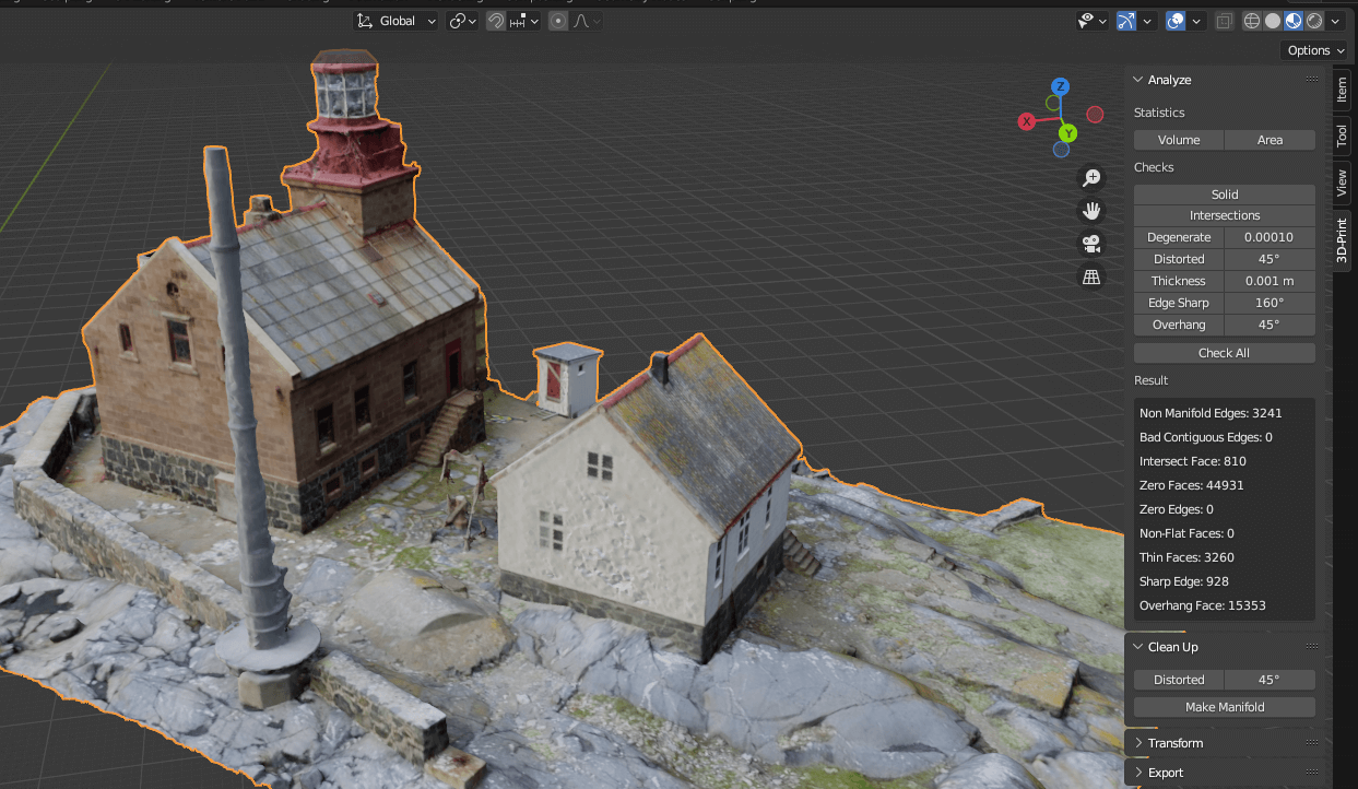
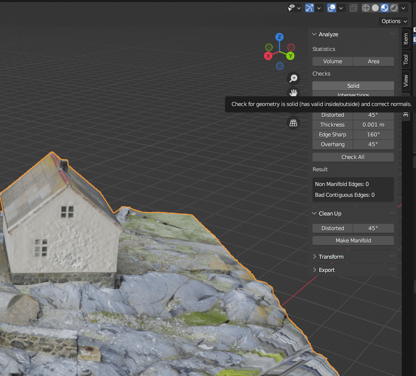
Let’s see what geometric properties of the 3D model Blender can show, click the “Check All” button.
It is worth noting that this plugin – as the name suggests – approaches geometric errors from the side of 3D printing. Almost all of the errors found in Blender’s “3D-Print Toolbox” summary can be fixed automatically, you can find a great documentation about them here.
BLENDER: FROM A 3D SURFACE MODEL TO A SOLID – HOW TO CALCULATE VOLUME AND SURFACE
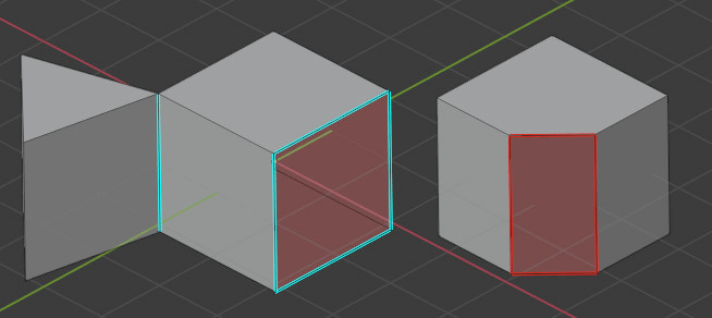
At the end of the previous chapter, out of the amount of details found in the “3D-Print Toolbox” summary, we should highlight two categories: “Non Manifold Edges” and “Bad Contiguous Edges”. What does Blender mean by these terms? Every edge must connect to exactly two faces. If it is connected to only one, it means that there is a hole in the mesh of the 3D model. Multiple connection points are not allowed. These non-allowed edges are called “Non Manifold” geometric elements. If the normal of one face points in a different direction than the adjacent faces, Blender marks these edges as “Bad Contiguous”.
The good news is, both geometrical errors can be corrected in Blender with 2 clicks ☺ First, within “3D-Print”, in the “Clean Up” menu, click on “Make Manifold” and then on “Distorted”. Just be careful, because both automatic corrections can take quite a few minutes, which of course depends on the hardware performance and the quality of the 3D model.
From the “Analyze” menu, click on the button labeled “Solid”, let’s see what Blender tells us, is our 3D model a surface or a solid? If you see the following under the “Result” section: “Non Manifold Edges: 0” and “Bad Contiguous Edges: 0”, then the process was successful, we have created a solid.
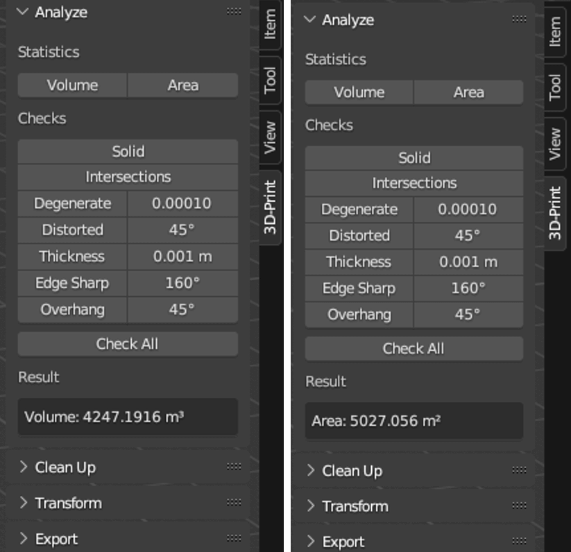
Let’s determine its volume and surface area. Within the “Analyze” menu, you will find the “Statistics” section, and here you will find “Volume” and “Area”. After clicking on them, the result will appear in a few seconds.
Sidenote: It is particularly gratifying that within “3D-Print” it is possible to scale the 3D model based on volume. For this, the “Transform” menu must be opened, and then under the “Volume” option, it can be specified to adjust the size of the 3D model to a specific volume.
FROM computer Graphics TO CAD: 3D MODELs FOR FINITE ELEMENT SIMULATION CALCULATIONS
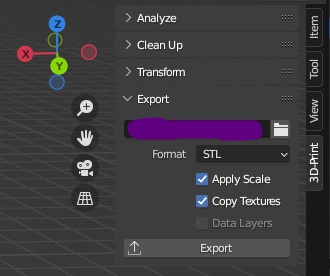
This chapter is for those who are very persistent or have already heard about finite element numerical modeling. What is this? In short: the finite element method (FEM) has spread among engineers. It is a numerical modeling technique that allows to simulate the response of a finite element 3D model with different impacts based on physical parameters. For example, the air resistance test or crash test of cars, the mechanical and load test of mechanical components. These simulation calculations have extremely high economic potential! Sticking to the car example, as long as an expensive and time-consuming car prototype is manufactured only to be crashed, in a virtual environment engineers are already able to fully optimize the car’s 3D geometry. The “3D-Print” used so far in Blender can also help with this! The solid 3D model can be exported in OBJ, PLY, STL, X3D formats. Select the 3D model, then from the “3D-Print” “Export” menu, first specify the location of the export by clicking on the folder icon. Set the target format and finally press the “Export” button.
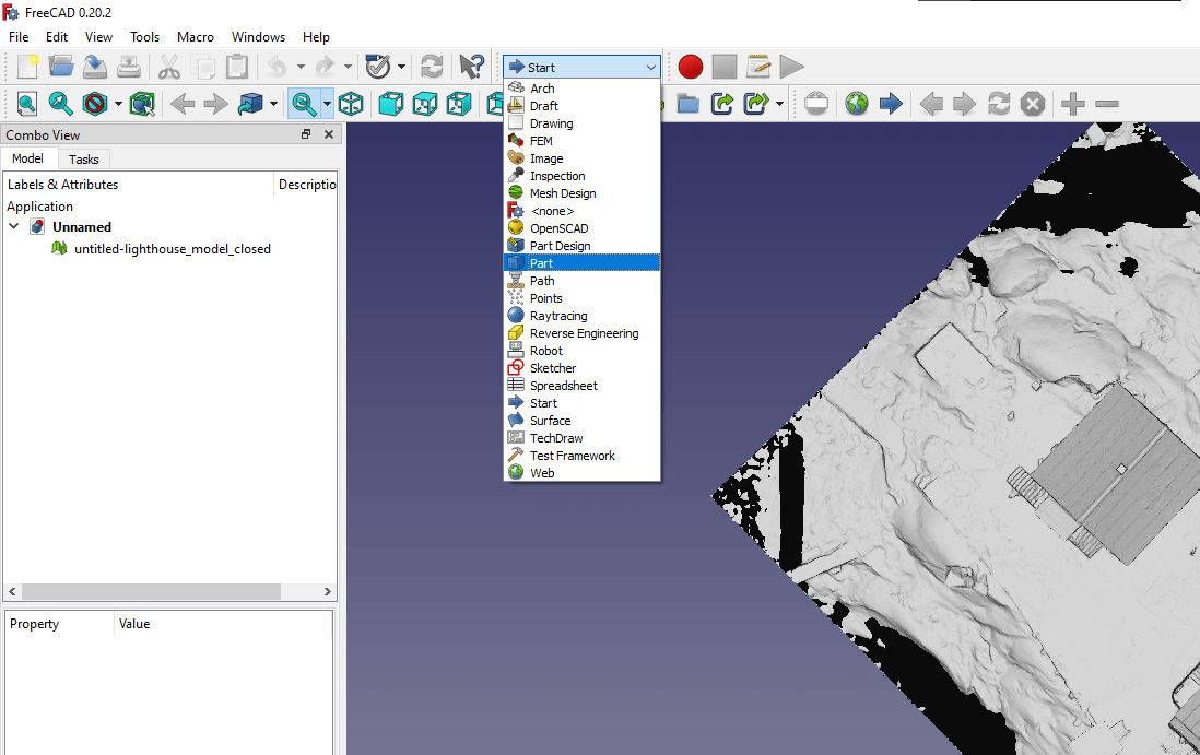
The question comes… Is there any free CAD software that can be used to perform simulation modeling even for learning purposes? If you are a regular reader of our blog, you probably know that we present almost exclusively free, open-source software, so that you can follow the steps along the way. We have just brought one of these, and this is FreeCAD. If you install and open a 3D model created in Blender, it doesn’t seem to interpret it as a solid, but you can easily transform it. Select “Part” from the drop-down menu containing action groups.
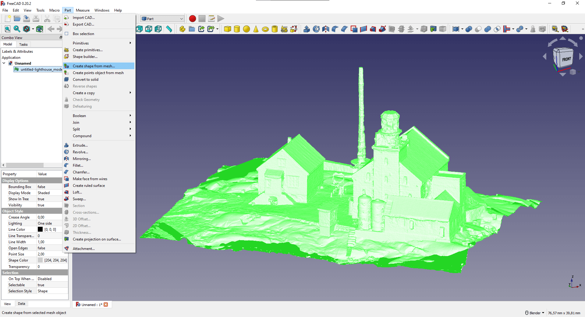
The “Part” menu appears in the top ribbon, select the “Create shape from mesh…” function. Run it with default settings, it may take a few minutes, drink a coffee in the meantime! 🙂
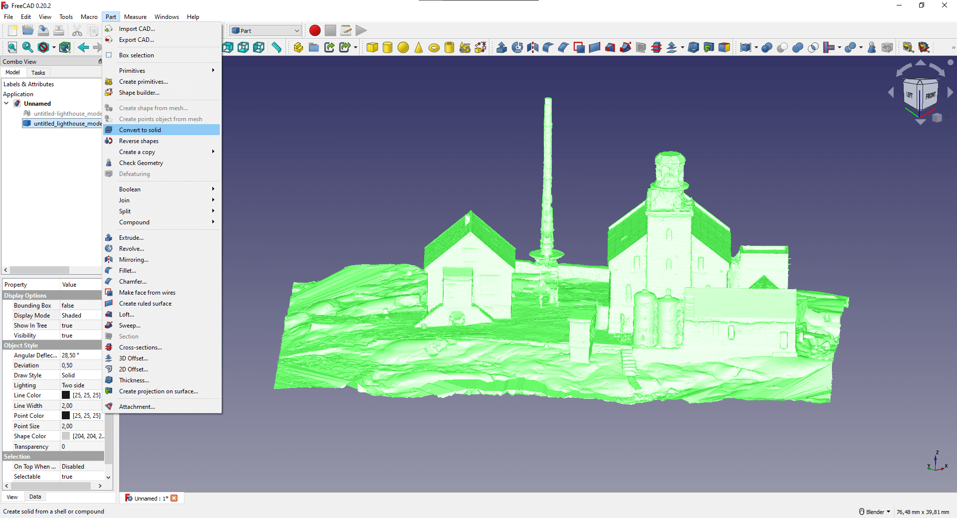
Also from the “Part” menu, select the “Convert to solid” option, with this you can create a solid 3D model that can also be interpreted by FreeCAD.
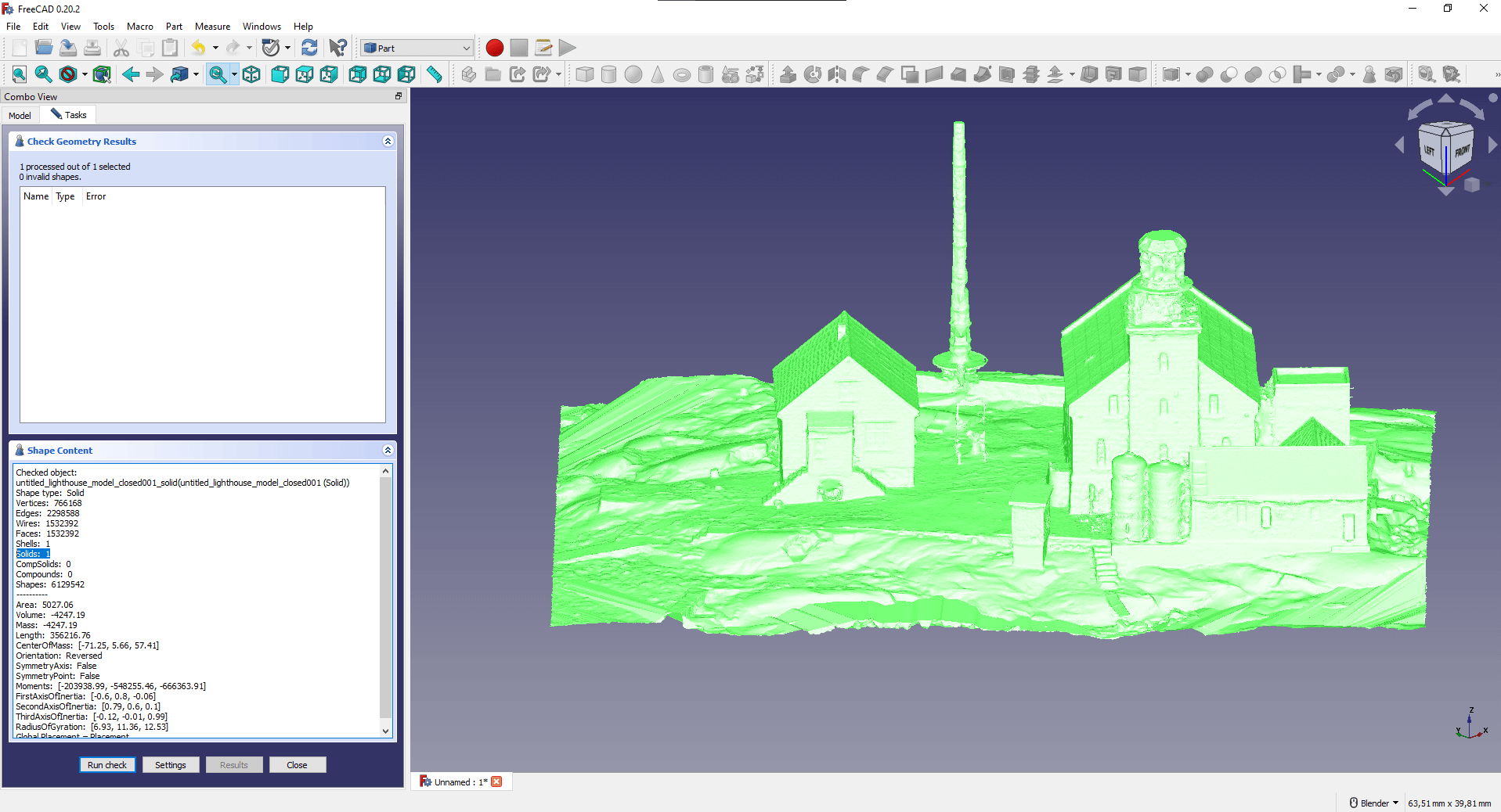
Finally, check whether the 3D model exported from Blender really is a solid. You can do this with the “Check Geometry” function of the “Part” menu. This operation can also take several minutes. I’m not saying drink another coffee here, but rather a tea? 🙂 In the menu bar on the left, you can see that “Shell: 1” and “Solid: 1” so the software interpreted the model both as a surface and a solid.
Numerical modeling is not our area of expertise, so we cannot write a blog article relevant to the parameterization, running and evaluation of the simulation model. However, if you have FreeCAD technical knowledge that you would like to share with others, write to us via our contact form on the web page or via the e-mail address [email protected]. If we find a topic together that fits into the scope of the blog, e.g., static examination of a building model surveyed with a drone, then we will publish your article! Be our next guest blogger, whom the professional audience will get to know! 🙂
Remember that you can improve your geometry with the help of “3D-Print”, but the large file size and the sharing of special files may still be a problem! We recommend that you follow the development of SurveyTransfer, a new generation of geospatial data sharing, HERE.
If you really liked what you read, you can share it with your friends. 🙂
Did you like what you read? Do you want to read similar ones?